Telescopes


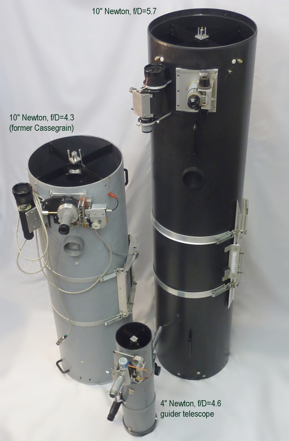
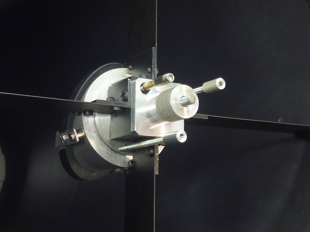
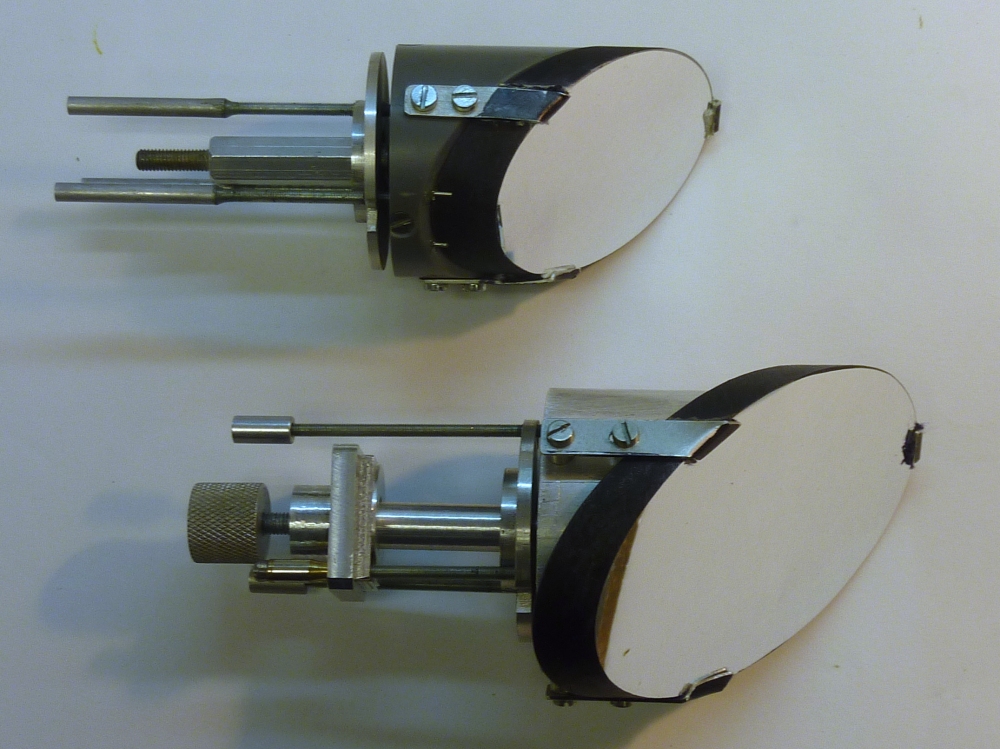
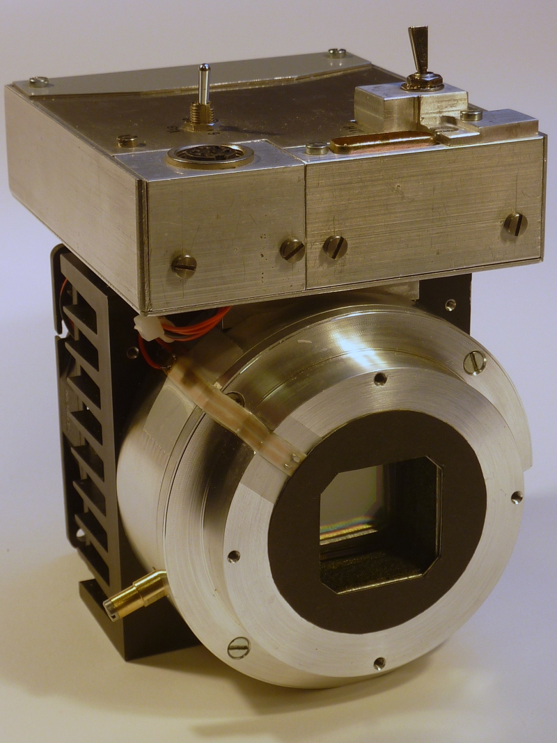
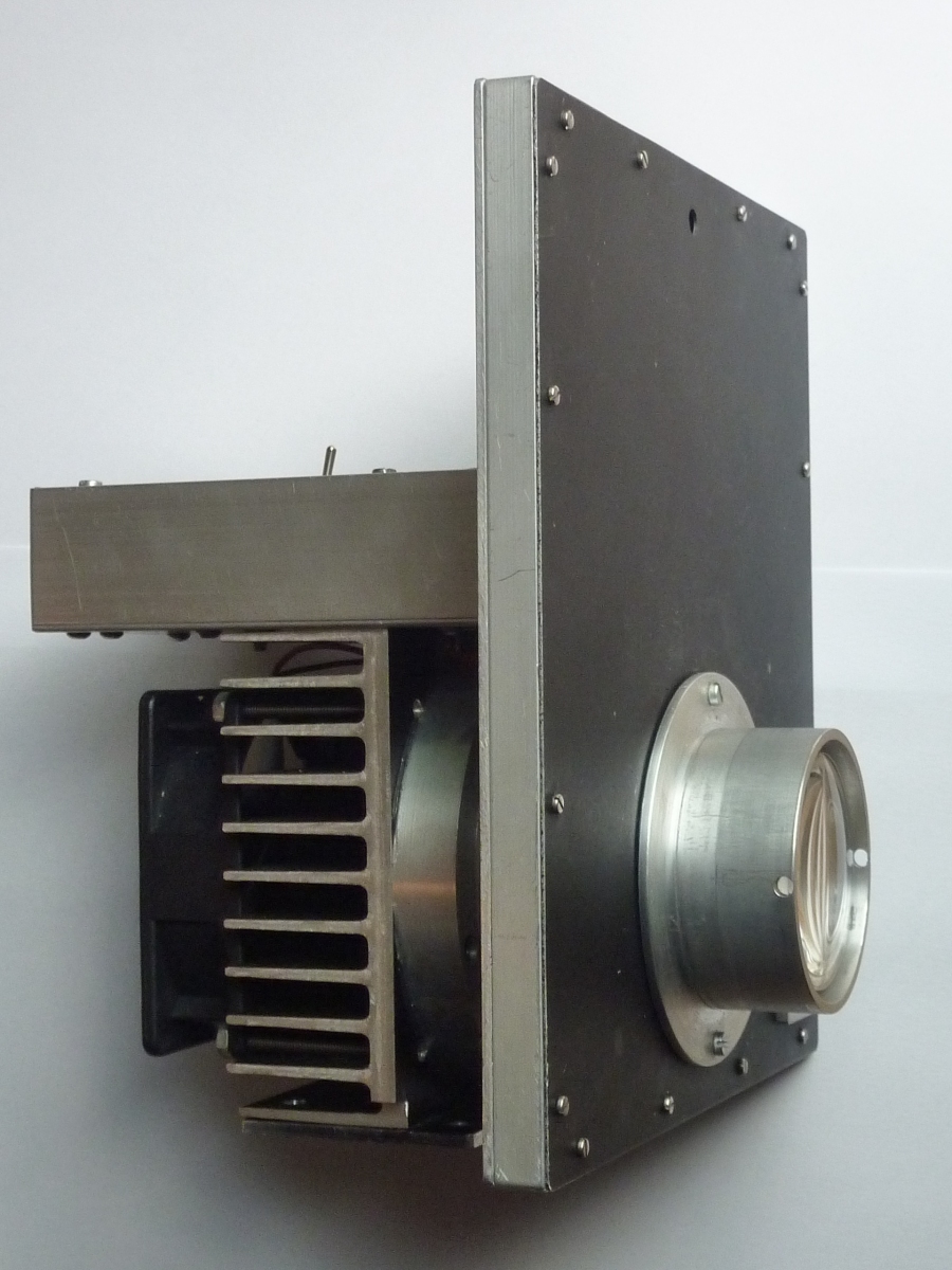
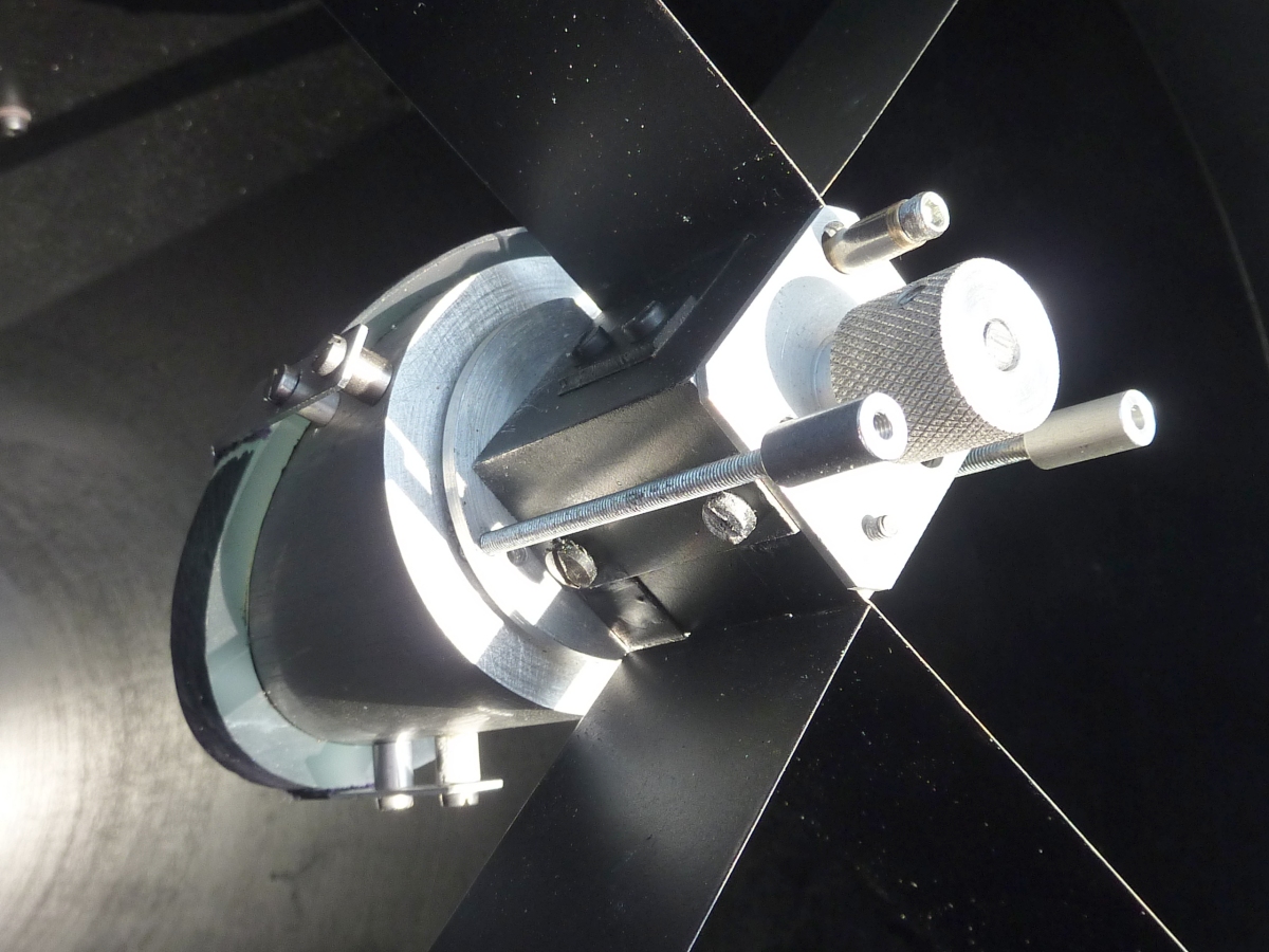
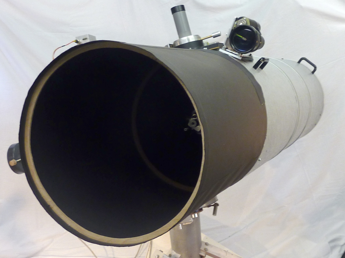
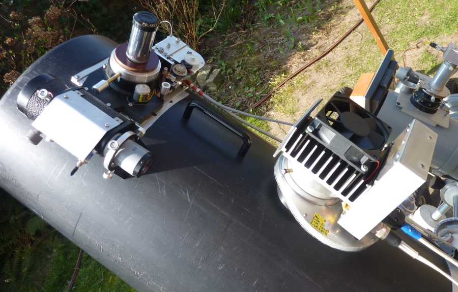
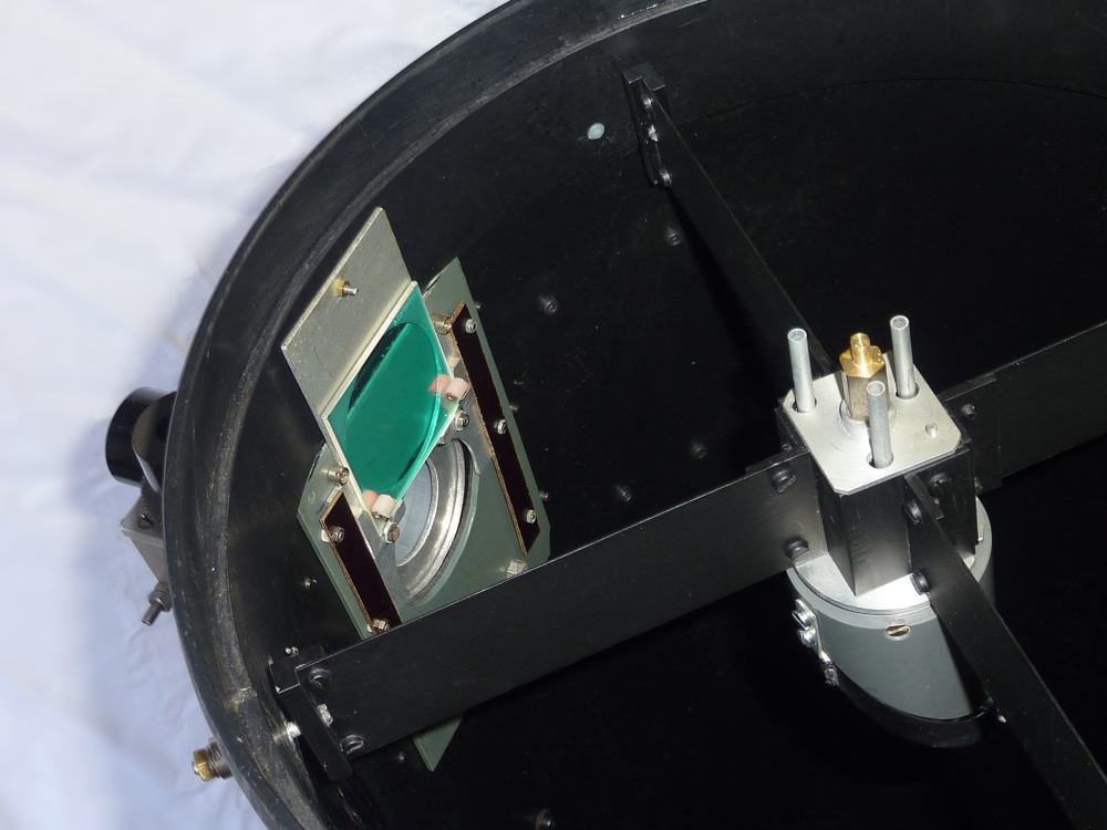
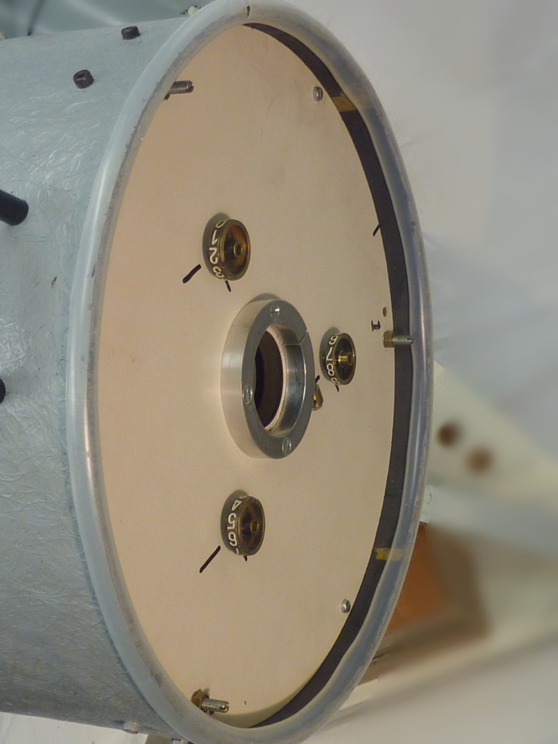
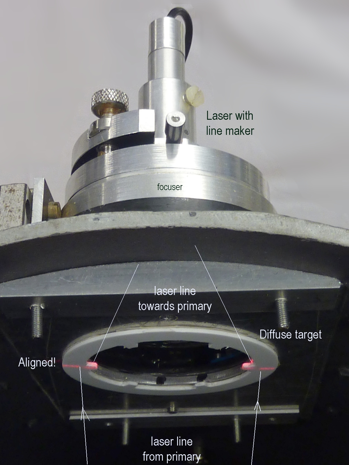
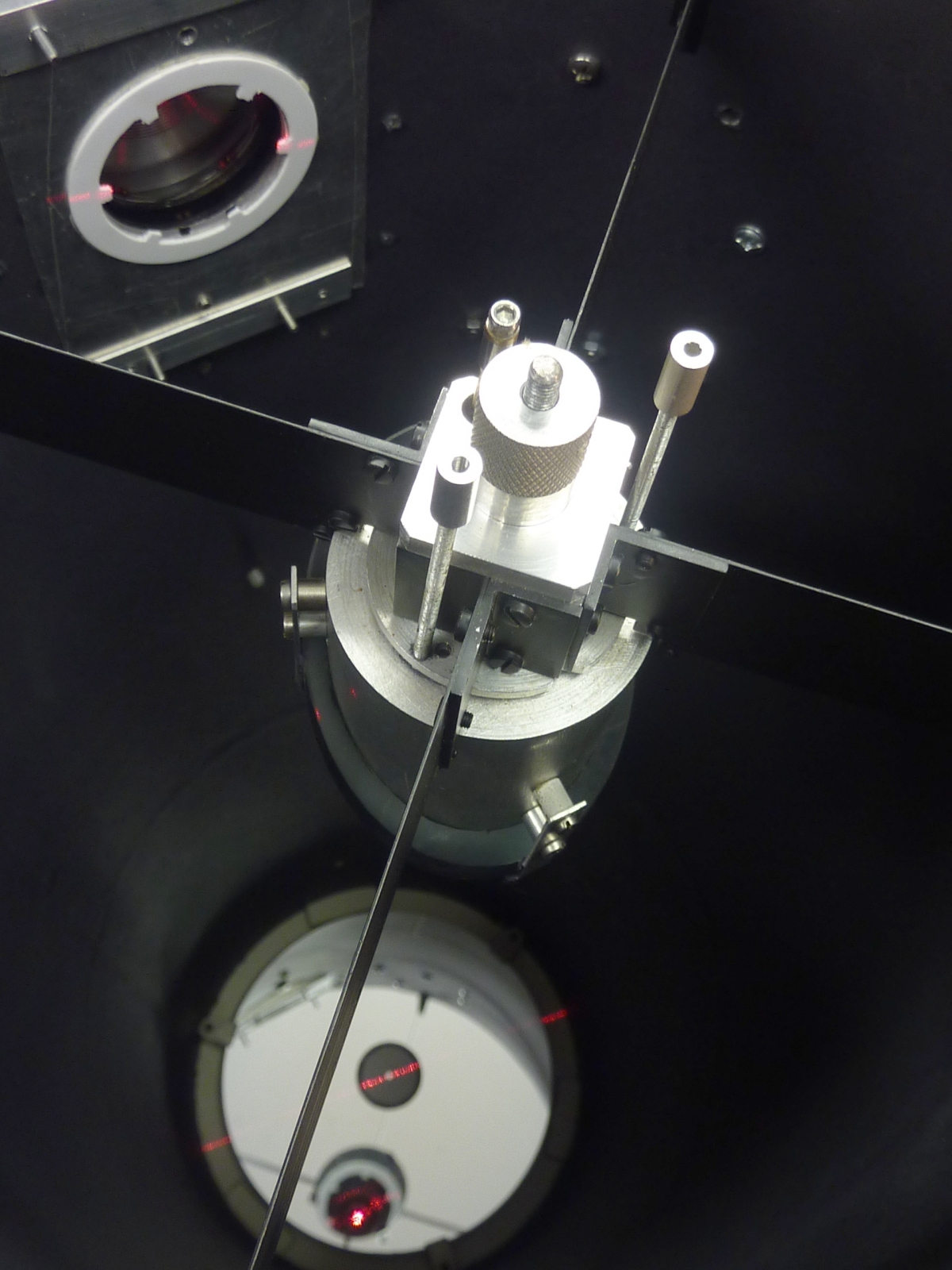
Over the years I've built 10cm (4" f/D=4.6), 15cm (6" f/D=6.3) and 25cm (10" f/D=5.7) Newton telescopes. A 25cm (f/D=16.8) Cassegrain model (initially meant for photographing planets at 4.3m effective focal length) was recently converted to a Newtonian configuration (f/D=4.3) which, combined with a miniscus lens as a simple coma-corrector and focal-reducer, has an effective focal length of 880mm at f/D=3.5. It is specially used for narrow band imaging with my 1kx1k FTT1010-M CCD-camera.
The 15cm telescope is currently out-of-use.

The 25cm f/D=5.7 telescope is used for LRGB- as well as narrow band imaging with the FTT1010-M or the 2kx2k FTF2020-M camera. With the latter camera the field of view measures 0.96x0.96 degrees. The 10cm telescope is solely used as an auto-guider and as an additional contra weight. For those who want to build their own telescope I highly recommend the already quite dated book "How to Make a Telescope" by J. Texereau.

The telecope tubes are made of PVC pipes except for the former Cassegrain type which is made of glas-fiber reinforced polyester.
Each telescope has the same mounting interface to which different types of focusers can be attached. The diagonal mirror for the 25cm telescopes is easily exchangeable: For the 24x24mm FTF2020 chip, the 25cm f/D=5.7 telescope requires a 70mm diagonal mirror. The same holds for the smaller 12x12mm FTT1010 chip on the 25cm f/D=3.5 Newton. For other applications a 50mm diagonal can be mounted. After replacement, the diagonal and primary mirror are aligned using a lasercollimator.


Telescopes in use
70mm diagonal & spider
50mm diagonal & drawing
Diagonal exchange
Focusing unit
Universal interface
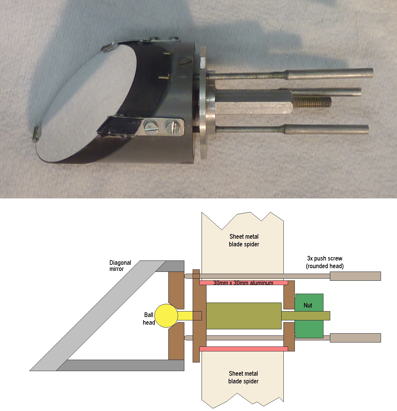
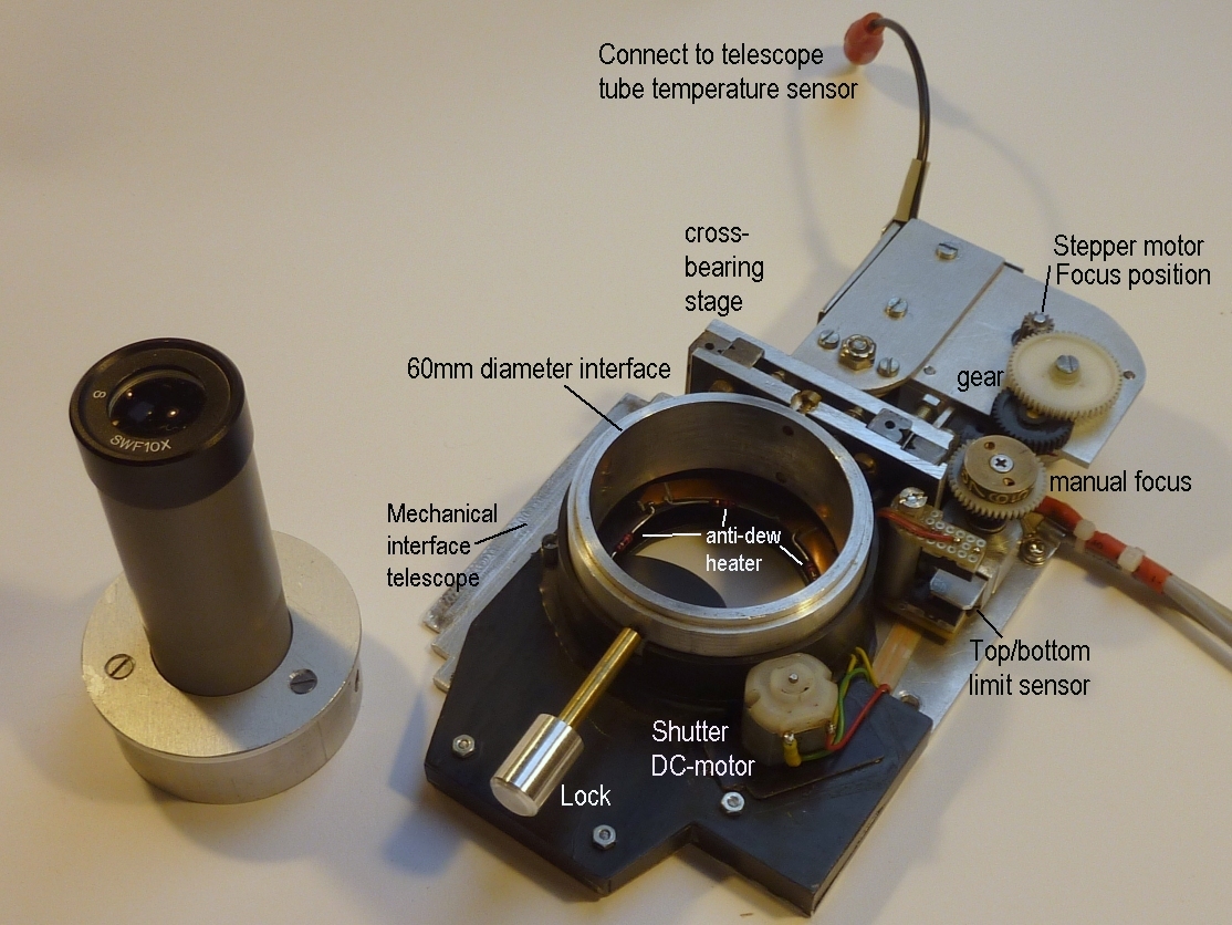
The images above give some more impressions and details. From left to right:
  • The three Newtonian telescopes grouped together. They feature the same mechanical interface for the focuser. The 10" telescopes have the same mechanical interface with the mounting plate of the equatorial mount.
  • A detail of the spider with mounted 70mm diagonal. The blades are made of galvanized, 0.7mm thick sheet metal (steel).
  • The central part of the spider is a 40mm length of a hollow 30x30mm aluminum profile. This allows for easy mounting and exchange of the 50mm or 70mm diagonals.
  • Mounting of the diagonal to the spider is demonstrated here.
  • The focusing unit features
    • a 60mm diameter 'receptacle' to accept the FTF2020-M or FTT1010-M camera nose pieces
    • a large shutter operated by a 12V DC-motor
    • internal heating to avoid dew build-up on filters or CCD-window
    • a z-stage with cross roller bearings
    • a stepper motor, gear and limit switches to enable focus control through i2c with the 'system controller'
    • connection to a temperature sensor built in the telescope tube. It is used to automatically correct the focus position for thermal expansion of the tube (via the same i2c-connection with the 'system controller'). For the PVC tubes, the thermal expansion can be some 50-80 micrometer per meter, degree Celcius.
  • Mounting of the focuser to the 'universal' interface of one of the telescopes
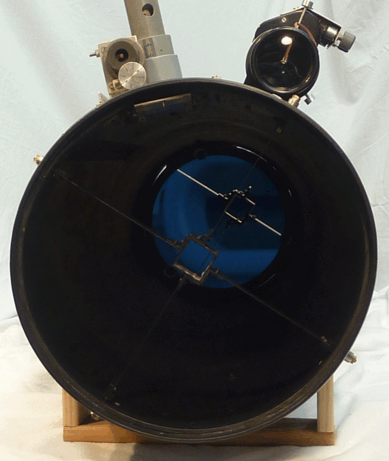
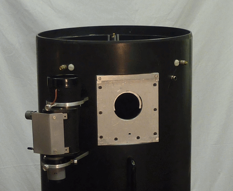
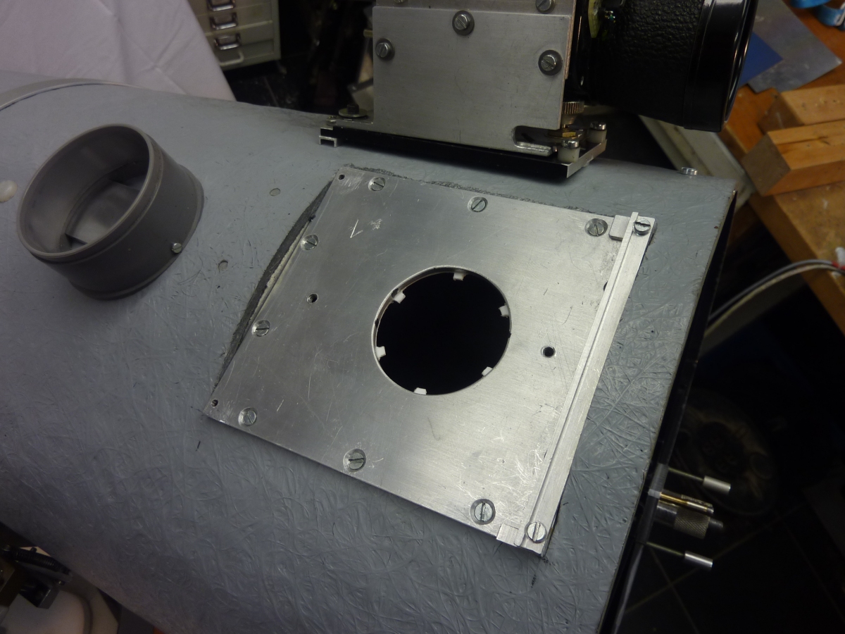
Some more images are shown below (from left to right):
  • The axial position of the saddle of the 10" telescopes can easily be adapted. Different positions yield a better balance over a wide RA-range for different declinations of the telescope. This balancing is needed due to the asymmetric loading of the telescope with the weight of the focuser+CCD-camera.
  • Note this older spider construction that was based on figure 58 of J. Texereau's book: It is to be avoided! Changes in tension on the spider blades, that may occur due to the weight of the diagonal in different orientations of the telescope, will cause a rotation of the diagonal. Use this construction instead.
  • Light shielding: The focuser is located relatively close to the top of the tube (especially for the modified Cassegrain with its 100cm long tube). As a result of this, the CCD-camera is exposed to light entering the top of the tube on the opposing side. A black carton cylinder, reinforced with two triplex rings, fits the tube end and adds an extra 40 centimeters to its length.
  • Sometimes a visual check or search for the object is needed, requiring the CCD-camera (with cables attached) to temporarily be exchanged for an eyepiece. A 60mm diameter 'receptacle' attached to the tube, near the focuser serves for parking the CCD camera.
  • Changing from narrow band filters to LRGB-imaging requires inserting an IR-filter. Currently the IR-filter is held in a manually operate slide attached to the inside of the focuser interface. Instead of the IR-filter, a 10x ND-filter can be mounted when photographing the moon.
  • This is just a nice photograph of the in 2022 recoated 10" f/D=5.6 mirror, taken and shared by Hans van Wigcheren of Stichting Sterrenwacht Almere
Adaptable saddle
position
Avoid this spider
construction!
Light shield
tube extension
CCD parking position
Manual IR-filter
10" mirror re-coated


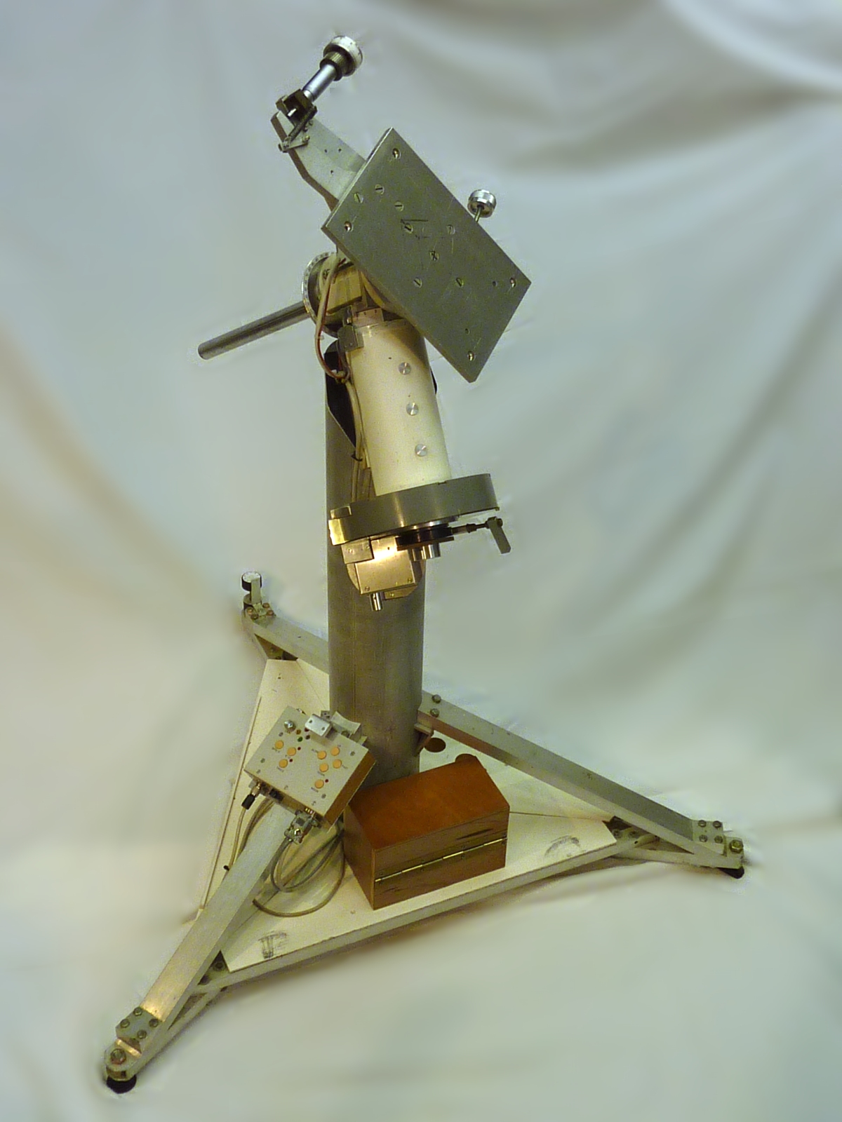
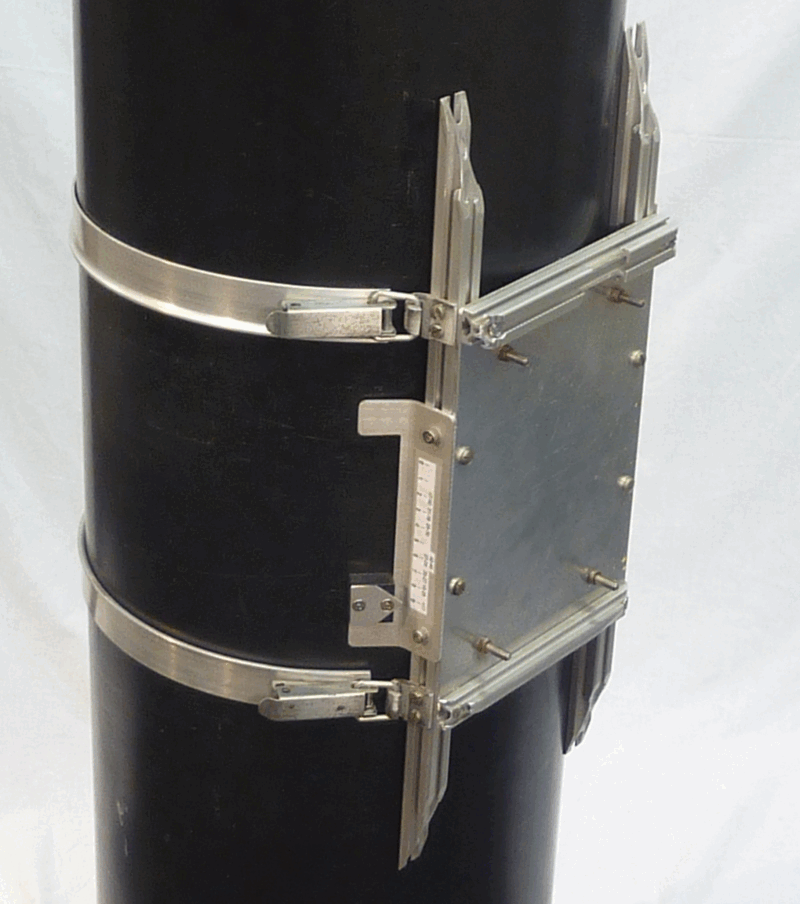
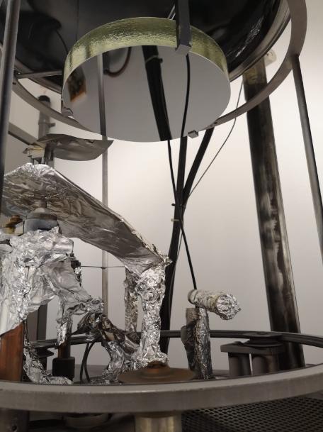
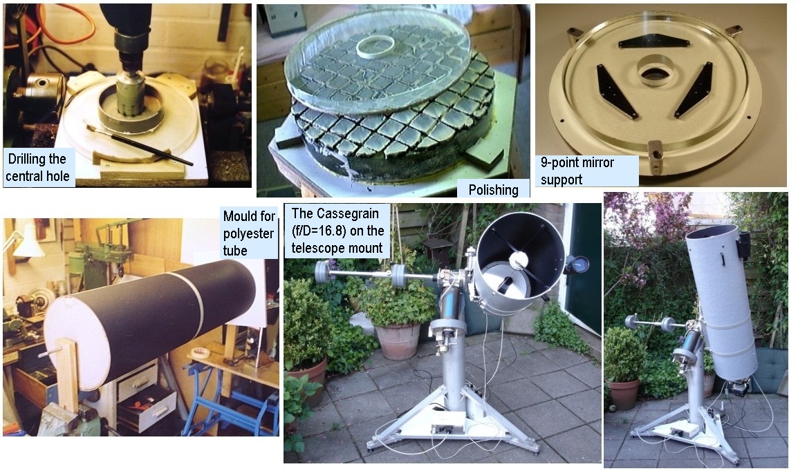
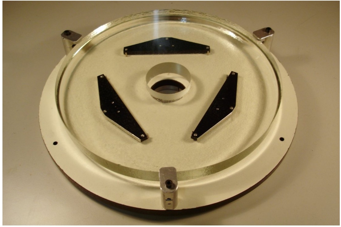
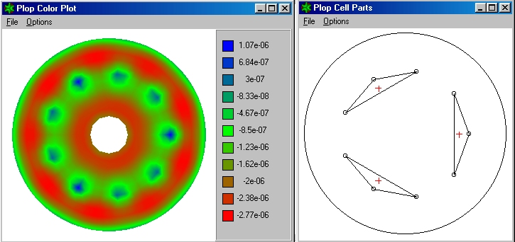
The following images give an impression of the 10" Cassegrain that was modified to a Newtonian telescope (left to right, again):
  • This foto collage shows the drilling of the hole in the primary mirror, the polishing of the primary, the 9-point mirror cell with uncoated primary, the card-board mould for constructing the fiberglas reinforced polyester telescope tube, and two photographs of the Cassegrain on the telescope mount.
  • The mirror cell with 9 support point in three groups, needed to support the relatively thin primary (21mm thickness),
  • The mirror deformation with the 9 support points, as calculated using PLOP (PLate Optimizer program for mirror cells): Peak-to-Valley error ~4nm. An article I wrote about using PLOP for designing this mirror cell appeared in Zenit 2005!, nr. 6, p. 294-297.
  • The three adjustment screws of the mirror cell carry a 0..9 scale to ease remembering position and direction of adjustments.
  • Collimation: since the central part of the primary is missing, the standard way of collimating a Newtonian, with a laser pointed to, and reflected off the center of the primary, is not useable. Instead, a line projection is used. See the laser collimator section.
Collage:
Cassegrain build
9-point mirror
support
PLOP simulation
results
Primary mirror
alignment screws
Collimation
Collimation