DESCRIPTION:
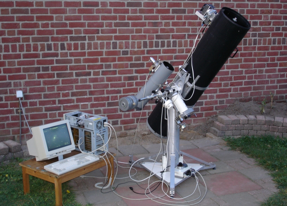
All equipment presented and discussed here is home built. The images below give an overview of the equipment I use, of which the different
parts will be discussed in more detail. Due to the modular set-up the equipment is mobile. Click on the nails to get the full
resolution image.
Currently I have three Newtonian scopes of different format: 11cm f/D=4.6 as a guider scope and a 15cm f/D=6.3
and 25cm f/D=5.7 for visual observations and CCD-photography. For those who want to build their own scope I highly recommend the
book "How to Make a Telescope" by J. Texereau.
The telecope tubes are made of PVC. At the position of the focuser each telescope contains the same mounting interface on which
different types of focusers can be attached. The diagonal mirror of the 25cm scope is easily exchangeable:
For illumination of the 12x24mm FFT1020 chip a 70mm diagonal is needed; for other applications a 50mm diogonal is mounted. After
replacement, the diagonal and primary mirror are aligned
using a lasercollimator. Back to top
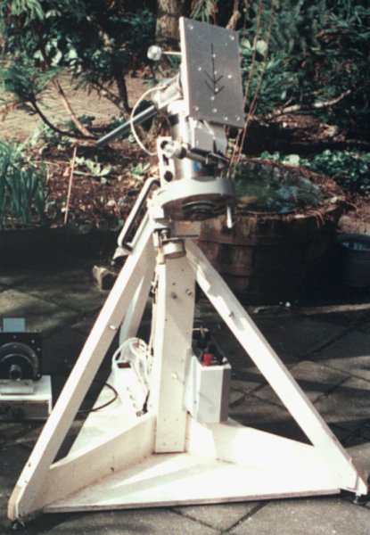
THE MOUNTING PIER
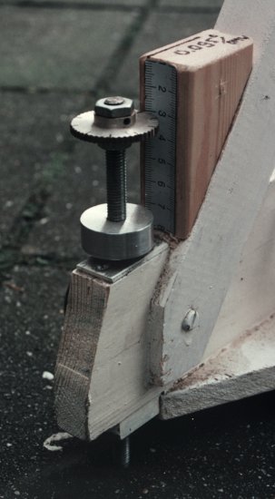
The mounting pier is made of wood and consists of a central pier (10x10cm) with three diagonal beams. On the mounting pier the
equatorial mount and control electronics for the drives are mounted.
One of the legs is adjustable in height in order to align the polar axis. With this feature the mounting pier can be used at
different location in my back-yard. At these positions there is a small hole in which the adjustable leg fits and a mark where
one of the other two legs should be positioned. The alignment of the polar axis then consists of adjusting the height of the adjustable
leg to a predetermined value using the scale and vernier. Back to top
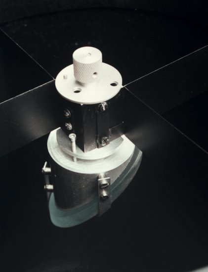
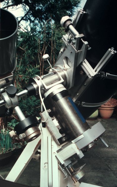
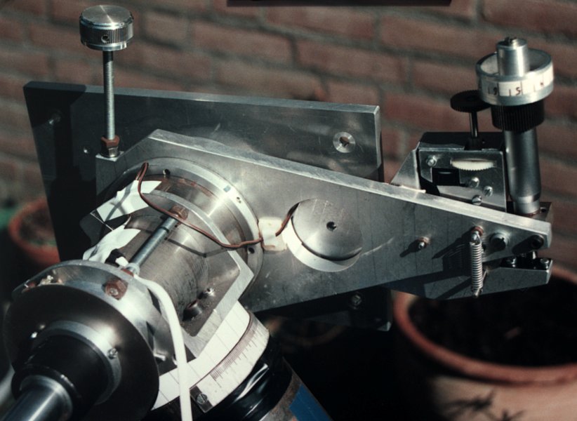
THE EQUATORIAL MOUNT
The worm-wheel is made on a lathe: With an M12-cutting tool in the jaw-chuck and, while pressing the free rotating brass wheel against
the M12-cutting tool, the worm-pattern is cut into the wheel. The worm itself is a piece of an M12 threaded bolt which is pressed
against the wheel and is spring-loaded. As with every worm-wheel (and especially this self constructed one) there is a periodic
error which is automatically compensated by using the guider scope.
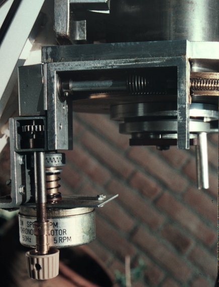
The worm is driven by a synchronous motor (230Vac/50Hz) via a gearbox. The speed of the motor is determined by a voltage controlled frequency
which is generated by the guiding system. The motor can be disengaged to position the polar axis by hand.
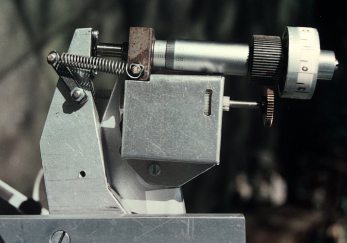
The declination axis can be tuned by hand, using a micrometer screw, or using a smal 12V DC-motor (which is coupled to the micrometer screw).
The large length of the declination correction arm enables accurate corrections to be made. The polar axis is 30mm in diameter and rotates
on two standard ball-bearings which are mounted in a 80mm diameter steel tube. The declination axis and bearing are from an old lathe.
The short, 40mm diameter axis is
extended with a 22mm diameter rod on which the counterweights and the guider scope can be mounted.
At the position where the declination axis is supported by the polar axis, a ball-bearing is formed by a ring of 4mm balls
around the polar axis. A small metal ring retains the balls around the polar axis. Back to top
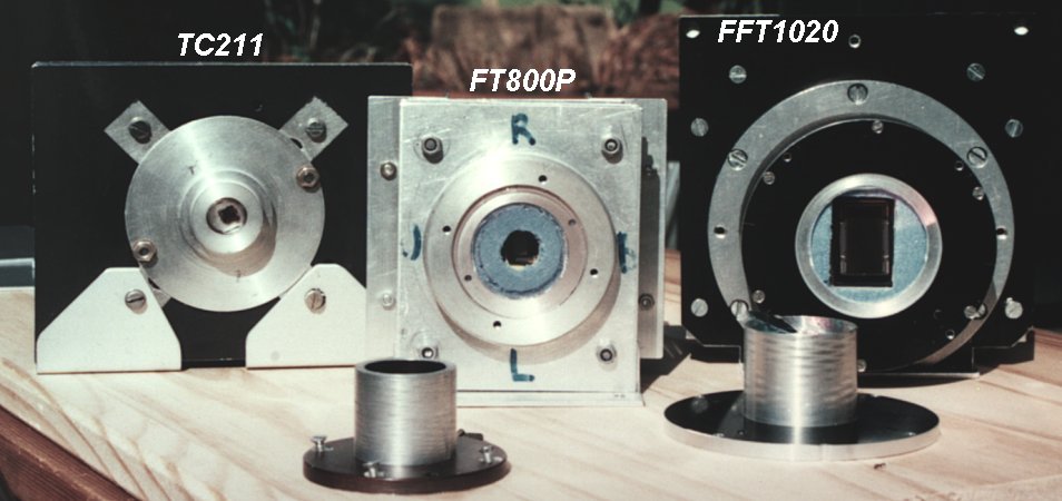
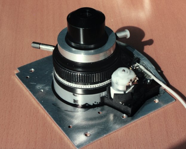
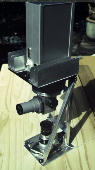
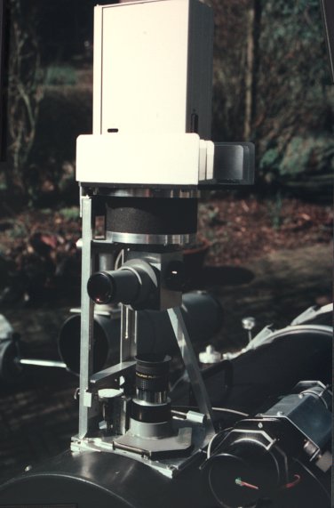
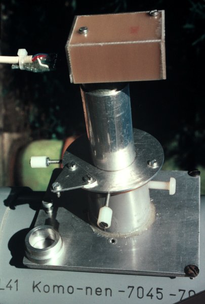
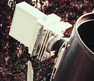
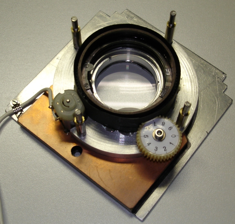
FOCUSERS
Two types of focusers are used. The focuser shown in the first image is made of an old camera objective of which all lenses are
removed and a 1.25" tube is inserted. A lever and numbered scale on the circumference ease focusing. A light-weight fane attached to the
axis of a small DC-motor acts as a shutter. This focuser is mainly used for full-frame exposures with the FTF1020 CCD.
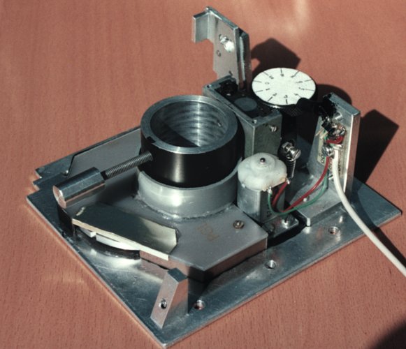
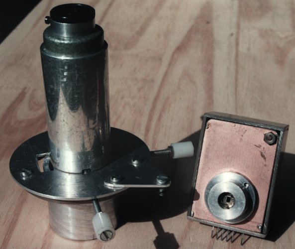
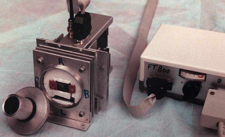
The focuser in the second image uses a small translation stage to which a 1.25" tube is attached. Under this tube, in a flat, for
light and dust shielded part, is a filter wheel with four positions (filters: Magenta, Yellow, Cyan and none) and a shutter of the
same construction as in the first focuser. The filter wheel is rotated by hand. This focuser is used for the FT800P CCD-camera and for
the FTF1020-C and FTT1010-M in frame-transfer mode.
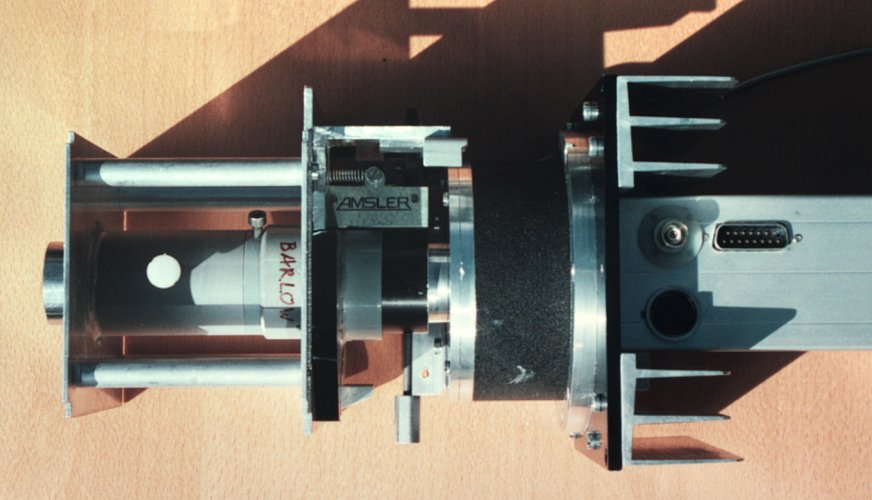
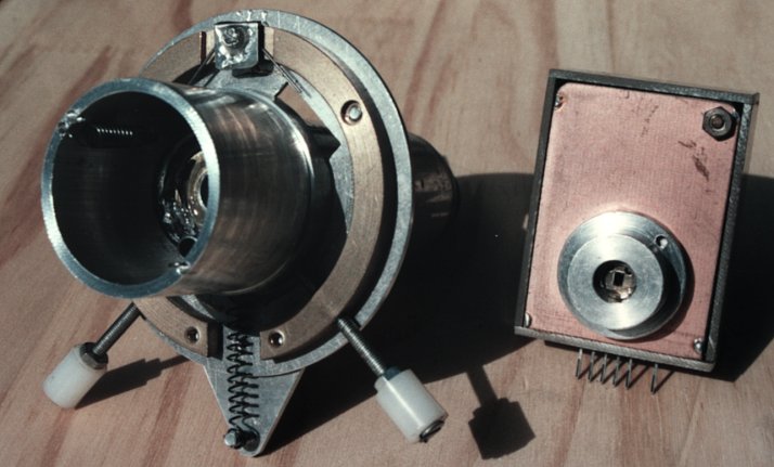
The other images show the focusers (with FTF1020-C camera mounted) as used with oculair projection and barlow projection (last
image). Back to top
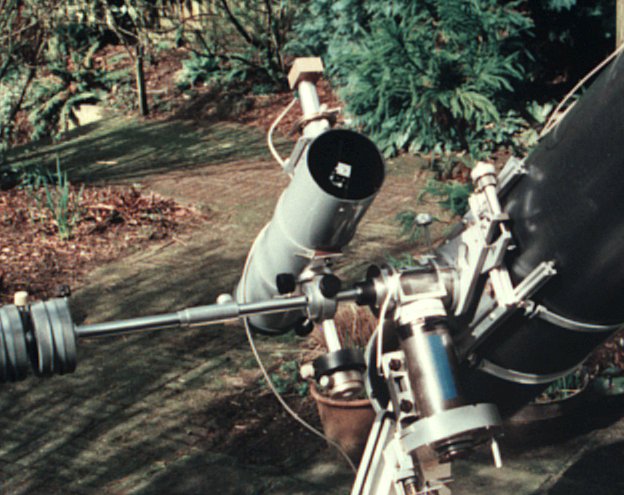
GUIDING SYSTEM
The worm and wheel combination shows a considerable periodic error of approximately 0.5'. To correct for this tracking error
the 11cm Newton scope is fitted with a duo-photodiode sensor and 'barlow lens' (a short focal length negatieve lens taken from an old
camera objective). The guiding scope is used as part of the counterweight and mounted on the declination axis. The barlow lens
significantly increases the focal length of the 11cm Newton.
A guiding star of magnitude +2 or less is positioned in between the two photodiodes (dimensions each: 0.5x1mm, gap: 0.1mm).
With the guide star exactly in between the two photodiodes the difference signal is zero. With a deviation of the polar-axis, the
left or right photodiode receives more light and a positive or negative difference signal results. This difference signal is
converted to a frequency using a VCO (Voltage Controlled Oscillator) which directly controls the speed of synchronous motor of
the polar axis. (For details see electronic controle and the sketch of the principle (upper right).
In order to freely select the guidance star, the guiding scope can be rotated over two orthogonal axis while remaining clamped
to the declination axis. Furthermore, the barlow+duo-photodiode combination can be positioned in the focal plane of the guiding
scope using an XY-slide mechanism. Before the duo-photodiode head is placed in position, the guide star is roughly centered by viewing
it through a small eyepiece. Back to top
ELECTRONIC CONTROLE
The control electronics resides in a box attached to the pier. It consists of a 230VAC->12V converter (12V battery operation is
also possible), the Voltage Controlled Oscillator and 12V->230VAC converter for the synchronous motor of the polar axes, driver
for the declination DC-motor, supply for the LEDs illuminating the circles and a LED for eyepiece-illumination.
The duo-photodiode guider and an optional manual controle box are connected to the electronics. Back to top
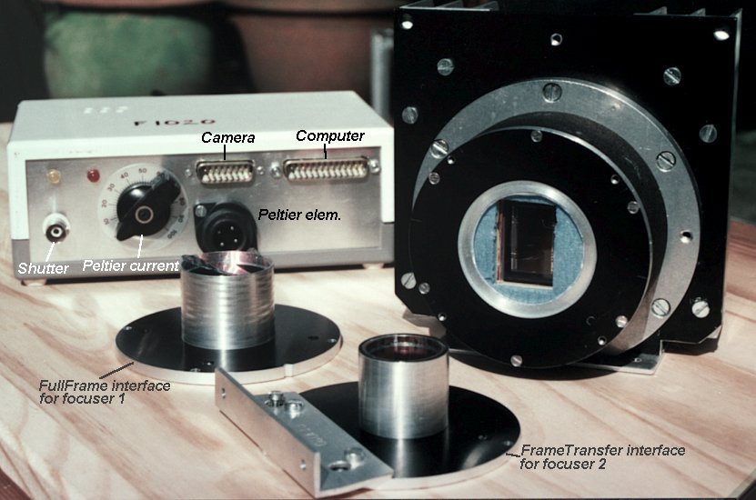
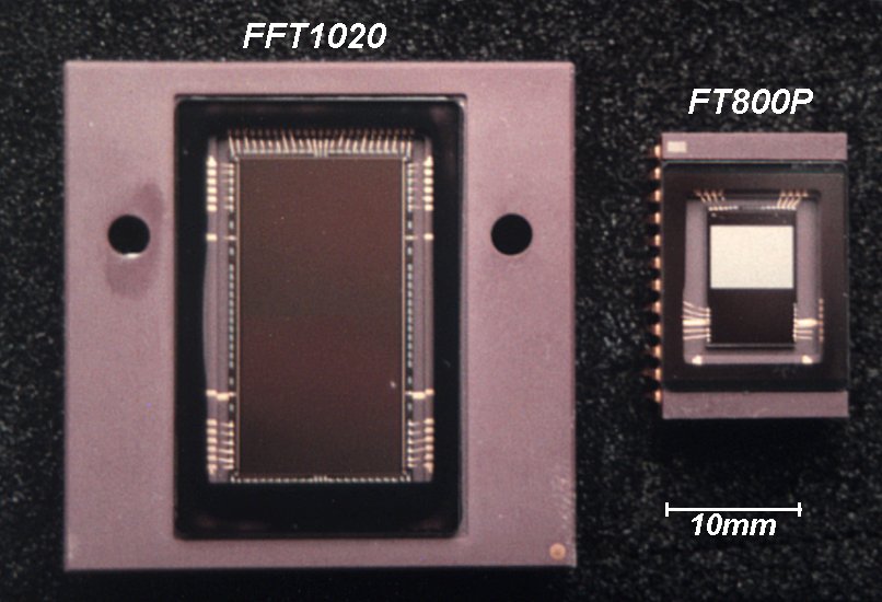
FT800P CCD CAMERA
This camera contains a Philips FT800P frame-transfer chip with a sensitive area of 6.4x4.8mm and 734x580 pixels, and a storage
section of the same size, but shielded from light by an aluminum shield. The chip is not used in interlacing mode and as a result,
the effective number of lines reduces from 580 to 290 of 16.8um height.
The width of a pixel is 8.5um. After acquisition of the image two horizontal pixels are added (binned) increasing the horizontal
pixel size to 17um.
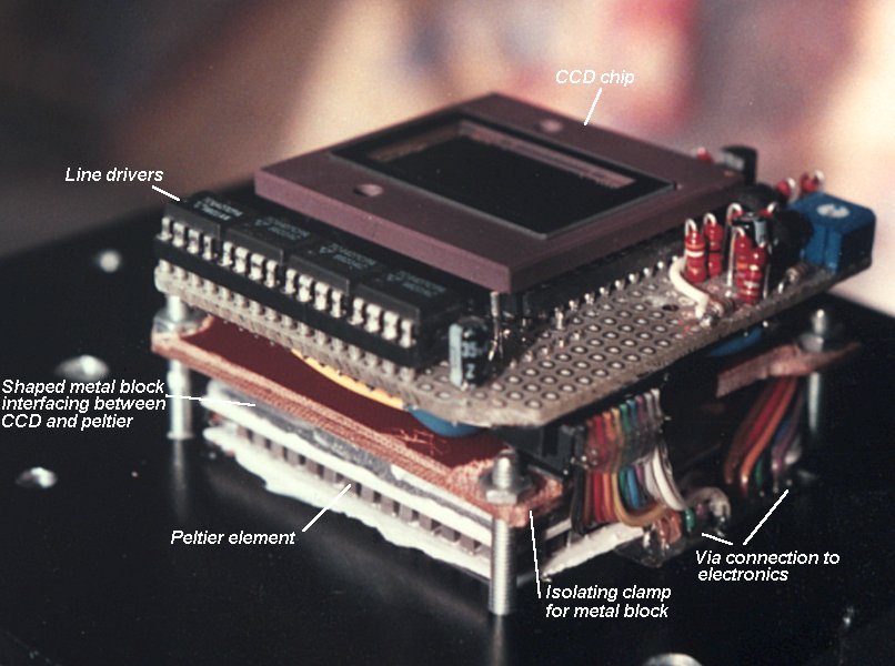
For cooling, the CCD-chip is attached to a thermo-electric element (Peltier element) via an aluminum block. On one side this block
is shaped to fit the CCD, on the other side it is shaped to fit to the Peltier element. Heat from the Peltier element is sinked
via the camera body to the attached cooling fingers.
The space surrounding the CCD, metal block and peltier element is stuffed with closed-cell foam for isolation and hermetically
sealed. As a window a multi-coated photographic UV-filter is used.
The power supply for the CCD-camera and Peltier element, a 12-bit AD-converter and digital IO (interfacing with the PC-printer port)
are apart from the camera in a separate housing. Back to top
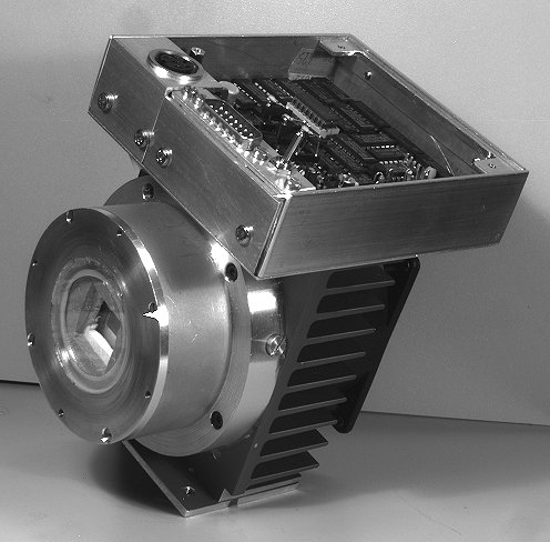
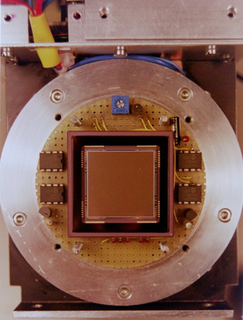
FTF1020 COLOUR CCD CAMERA
This camera uses the FTF1020 full frame chip with 1024x2048 pixels of 12umx12um. The surface of the chip is covered with
a colour filter consisting of red, green and blue filters in a so-called Bayer-pattern (odd lines: RGRGRG...; even lines GBGBGBGB....).
The chip therefore has 512x1024 colour pixels of 24x24um. As with the FT800P camera the CCD is attached to a Peltier element via a metal block, fully isolated and hermetically sealed.
Heat is led to a heat-sink on the back of the metal plate on which the Peltier element is mounted.
When making colour images an external heat-reflecting (i.e. IR-blocking) filter is used in order to obtain a correct colour
balans. If not used, roughly half of the sensitivity at each colour originates from infra-red radiation with a wavelength
larger than 700nm.
Compared to the FT800P camera there are a few advantages as well as disadvantages of a colour CCD to be pointed out:
When imaging planets and the moon the colour-CCD has the advantage of grabbing a colour image with only one exposure.
In the presence of admospheric turbulance only a short moment of good seeing is required to capture a sharp image. Problems with
stacking RGB-exposures of the fast rotating Jupiter, which already after a few minutes in between the shots do not fit well,
does not occur with the colour chip.
Due to the large area of the FTF1020-C chip (12x24mm), locating objects within the field of view is simple and larger
objects can be photographed.
As a result of the integrated RGB-filter the sensitivity of the CCD is lower. In part this is compensated by the fact that
for a colour exposure with a filter wheel three exposures are required. In the total exposure time of these three exposures the
colour CCD nearly comes to the same signal strength.
It is useless to try to capture H-alpha objects with FTF1020: When using a H-alpha filter only the R-pixels are active
and the remaining chip area is unused. Monochrome chips have a significant advantage here.
Not blocking then 700-1000nm range leads to incorrect colour balance since the colour pigments of the integrated filters are
inactive in the infra-red.
After some time experimenting and using the FTF1020-C camera, a few drawbacks of the colour-chip showed up:
The sensitivity is good for acquiring images of moon, planets and bright nebula such as the Orion nebula, Dumb-bell nebula and Ring nebula.
For galaxies the sensitivity is just a little too low and long exposures are necessary (often more than an hour is required). Then, still significant noise
in the image remains.
When using an H-alpha filter or colour filter, in order to increase contrast and suppress nightsky glow, the sensitivity drops dramatically
since only part of the chip area is sensitive in the spectral range of the used filter.
With sharp images of stars only one of the three colour pixels is activated, giving a false overall colour. An open cluster of stars becomes a wild collection
of unnaturally coloured objects.
The FTT1010-M and FTF2020 monochrome CCDs do not have these draw-backs and, in addition, the following advantages:
Without filters, the sensitivity of the chip-area is 6 to 8 times larger.
When using MYC-filters, available light is more efficiently used than with on-chip RGB-filters. Also a better
colour balance is more easily obtained.
The FTT1010-M and FTF2020-M CCD's are functionally identical to the FTF1020-C chip. The design of the camera is improved to obtain
a more efficient cooling of the CCD-chip. Just as with the design of the well-known Audine camera, the peltier element is
mounted on a big heatsink that is cooled by forced air from an attached fan. The peltier-element itself is a smaller and a more efficient
type (Melcor 30x30mm). Back to top
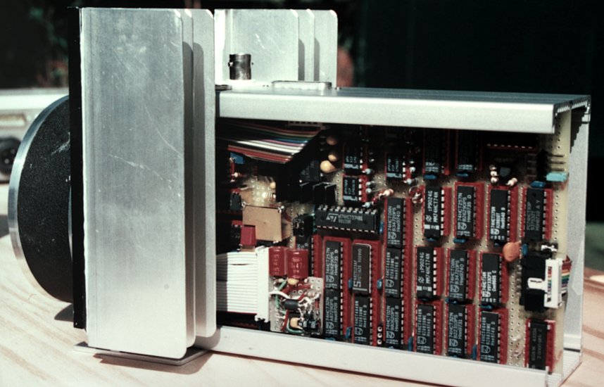
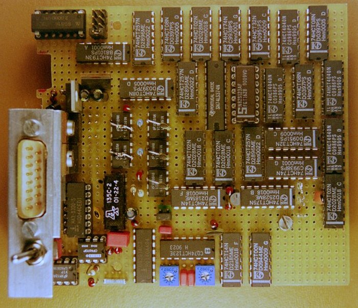
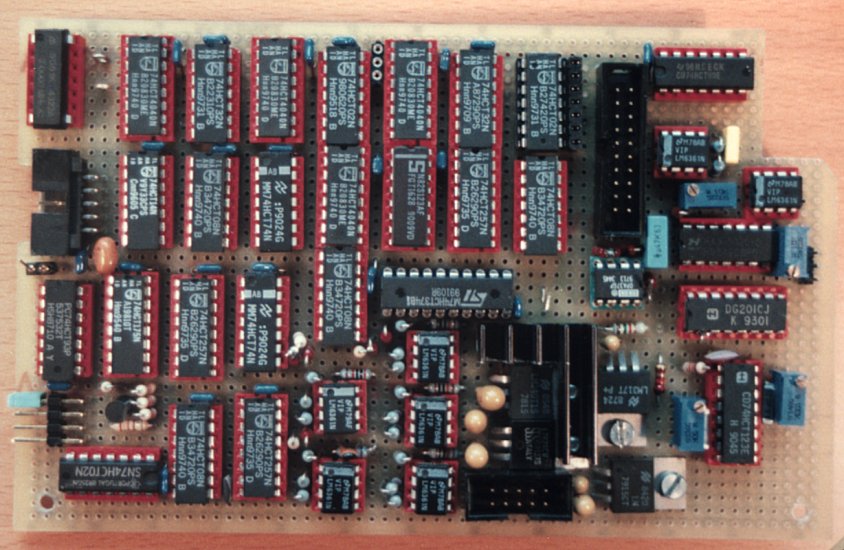
CAMERA ELECTRONICA EN AD-OMZETTER
The functional lay-out of the electronics of all cameras is comparable. Drivers for the vertical shift registers (A and B gates)
and the horizontal register (C gate) are in the vicinity of the CCD-chip. With these gates the charge that has accumulated during
exposure is shifted line-by-line (A,B) and pixel-by-pixel (C) to the on-chip charge-to-voltage converter. This signal is buffered
with an external emitter follower to obtain a low-ohmic output and protect the sensitive output of the CCD.
The electronics board inside the camera mainly contains digital circuits with the following functions (inputs/outputs):
CLEAR: Drive all gates low to drain accumulated charge and clear the CCD.
READ (as opposed to INTEGRATE): FT800P, FTF1020-C, FTT1010-M in Frame Transfer mode: Shift the accumulated charge to the shielded storage area
(3 millisec) and start clocking out charge to the output. For the FT800P and FTT1010-M the shielding is on-chip; for the FTF1020-C an external shield
is used. FTF1020-C and FTF2020-M in Full Frame mode: Start clocking out charge to the output (pixel clock: 333kHz).
BINNING (not FT800P): On-chip binning (i.e. adding) of 2(H)x2(V) pixels increases sensitivity by a factor 4 at the cost
of resolution. The image resolution reduces in both dimensions by 2 and the pixel size becomes 24x24um.
SAMPLE: This output gives the pixel clock and is used to synchronize the AD-conversion process. For the FT800P the
conversion cycle is 38usec per pixel; for the FTF, FTT chips it is 3usec.
A small part of the camera-board consists of an analog circuit for processing the video signal. It contains a 1x/3x/10x
AC-coupled amplifier and a sample-and-hold circuit that uses Correlated Double Sampling.
Description of the AD-convertor:
The S&H output is fet to a 12-bits (0..4096) analog-to-digital convertor. In case of the FT800P this AD-convertor, together
with the I/O-drivers for the digital functions and the camera power supply are housed in a separate box. Data-transfer and
camera controle is via the printer port. In case of the FTF and FTT cameras the ADC and I/O are on a board inside the computer
(133MHz Pentium PC) which is connected to the ISA slot. Back to top
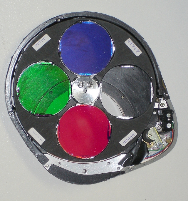
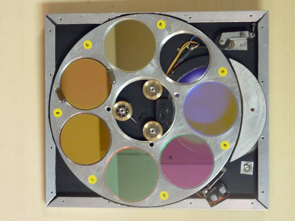
RGB and SHO FILTER WHEELS
My first filter wheel has 4 positions of which three are used for a Magenta, Yellow and Cyan filterset (Edmund Optics). The fourth
position is open. When using the filter wheel an infra-red blocking filter is used in front of the CCD-camera.
Due to the large size of the FTF2020-chip (with a diagonal of 35mm) the filters are of 50mm diameter. The filter wheel is flat
and only adds 4mm to the total path length. The construction is shown in the schematic drawing on the right.
I recently constructed a 7 position filter wheel with narrow band SII, H-alpha, OIII, R, G, B filters and an open position.
The mechanism for rotating both filter wheels is kept simple: A DC-motor and rubber pressure rol from a recorder are used for
the rotation. A micro-switch that acts on the four notches in the circumference of the wheel interrups the power to the DC-motor
and stops rotation. With an external switch (transistor) the micro-switch is temporarely short-circuited and power is applied
to the motor, starting rotation until the next notch. (The notches are not visible in the above images since they are alongside
the lower rim of the wheel.)
Care should be taken that the micro-switch not only interrupts the supply to the motor but also (nearly) short-circuits the
motor in order to force it to a quick hold. Otherwise inertia of the motor and wheel may be enough to keep it rotating during
the short interruptions of the micro-switch. Back to top
SIMPLE COMA-CORRECTOR AND FOCAL REDUCER FOR H-ALPHA
When using the H-alpha filter (656nm, 10nm bandwidth) only one color is present and the chromatic aberration of a lens is negligible.
By adding a simple plano-convex lens the coma of the Newton telecope can be reduced while at the same time the field of view
and the sensitivity can be increased.
The first drawing shows a detail of the optical lay-out of the f=1455mm, f/D=5.7 Newton
scope. It shows the secondary mirror and the CCD-chip in prime focus, with in front of the chip the window of the CCD-camera
and the H-alpha filter (Edmund Optics). The second drawing shows the same detail now with
an additional plano-convex lens which acts as a coma corrector and focal reducer. In my case it is a BK-7 Edmund Optics lens with a
focal length of 250mm (45154). The lens and its position are optimized using the ray-tracing program Zemax and accounting
for some mechanical constraints.
The result is a reduction of the spot size with a factor 2, up to the very edge of the FTF2020M CCD (24.5x24.5mm), and an increase
of the sensitivity from f/D=5.7 to f/D=4.7 (a factor 1.5). The field of view with the FTF2020M is increased from 0.96°x0.96°
to 1.14°x1.14°.
The drawing on the right gives the ray-tracing results (spot shapes) for the
configurations with and without the 'corrector'-lens. The small black circle in each spot diagram is the Airy-disc
(the diffraction limit). Spot number 4 is the one in the diagonal corner of the CCD. Back to top
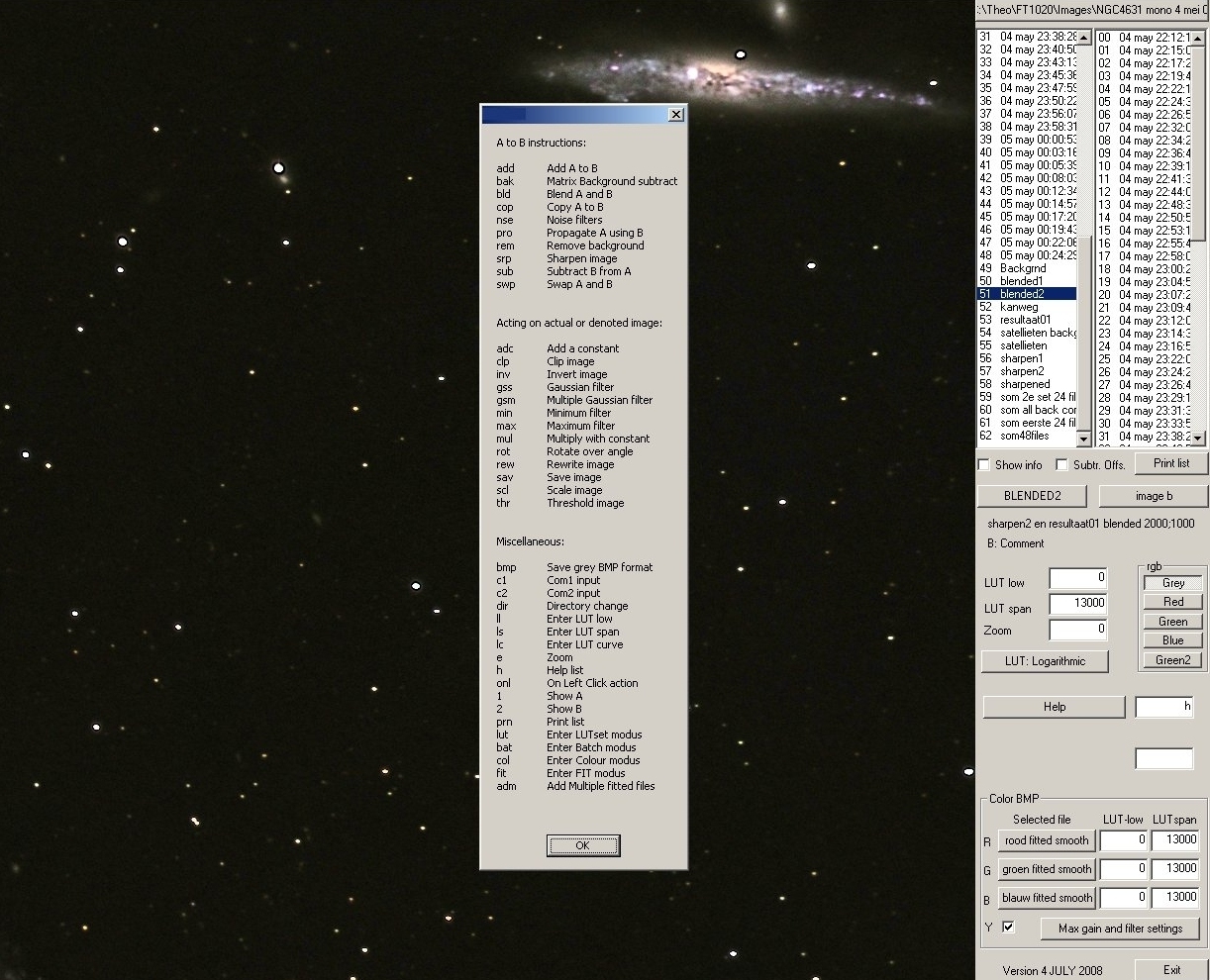
SOFTWARE FOR IMAGE PROCESSING
Software for processing of the CCD-images is developed in MicroSoft Visual C++. Two images can be selected (denoted by A and B). It is possible
to process A and have the result in B, or to do arithmetics with images A and B resulting in B. Also, R,G and B-images can be selected for obtaining
a colour image while A or B can be selected as the luminance component (Y-image).
The screendump below shows the help-message dialog with the most important functions and instructions.