Guider telescope and 4Q-sensor


The home-made worm and wheel combination suffers a - more or less - periodic error of approximately 0.5'. To correct for this tracking error the 11cm Newton scope is fitted with a 4-quadrant sensor and 'barlow lens' (a short focal length negatieve lens taken from an old camera objective). The guiding scope is used as part of the counterweight and mounted on the declination axis. The barlow lens increases the 0.5m focal length of the 11cm Newton to approximately 1.9m.

The 2mmx2mm surface area of the 4Q-sensor covers a maximum field of view of 0.06 degrees. The sensor measures the deviation in East/West and the North/South direction of the guide star from the center of the 4Q-sensor. This deviation is used to control the frequency of the RA-stepper motor and the (future) declination DC-motor such that the guide star remains centered.

Images below give some more details. From left to right:
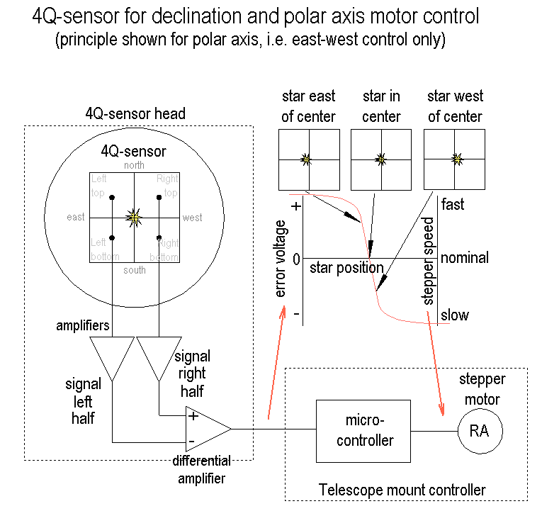
  • The principle of the 4Q-sensor and guiding is depicted here:
    The difference of the star's contribution to the summed left (east) quadrants and summed right (west) quadrants, yields a signal that is 0 (zero) with the star centered between left/right halfs and steeply rises with the star deviating to the east or sharply drops when deviating to the west. This 'error' signal controls the RA-stepper frequency. In my case the correction of this frequency is generally in the +/-4% range.
    The difference in summed top quadrants and bottom quadrants can be used to control the declination drive. I use it to keep the quide star centered on the 4Q-sensor using the small stepper attached to the North/South adjustment screw.
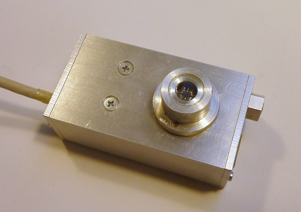
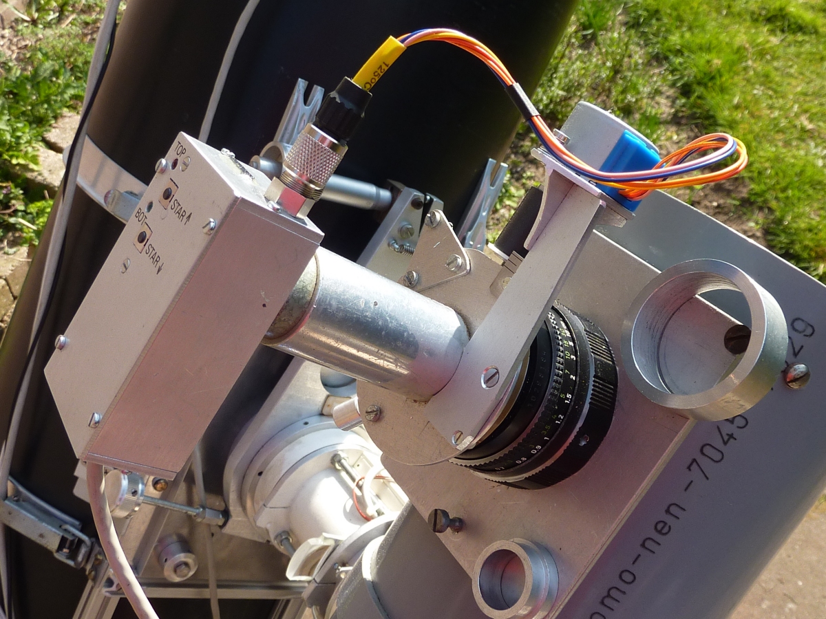
  • The 4Q-sensor is visible here. The 4Q sensor head contains high gain transconductance amplifiers (i.e. photo-current to voltage convertors), Left/Right and Top/Bottom summing and difference amplifiers and a controller for the Top/Bottom centering stepper. The schematics may give you some more insight.
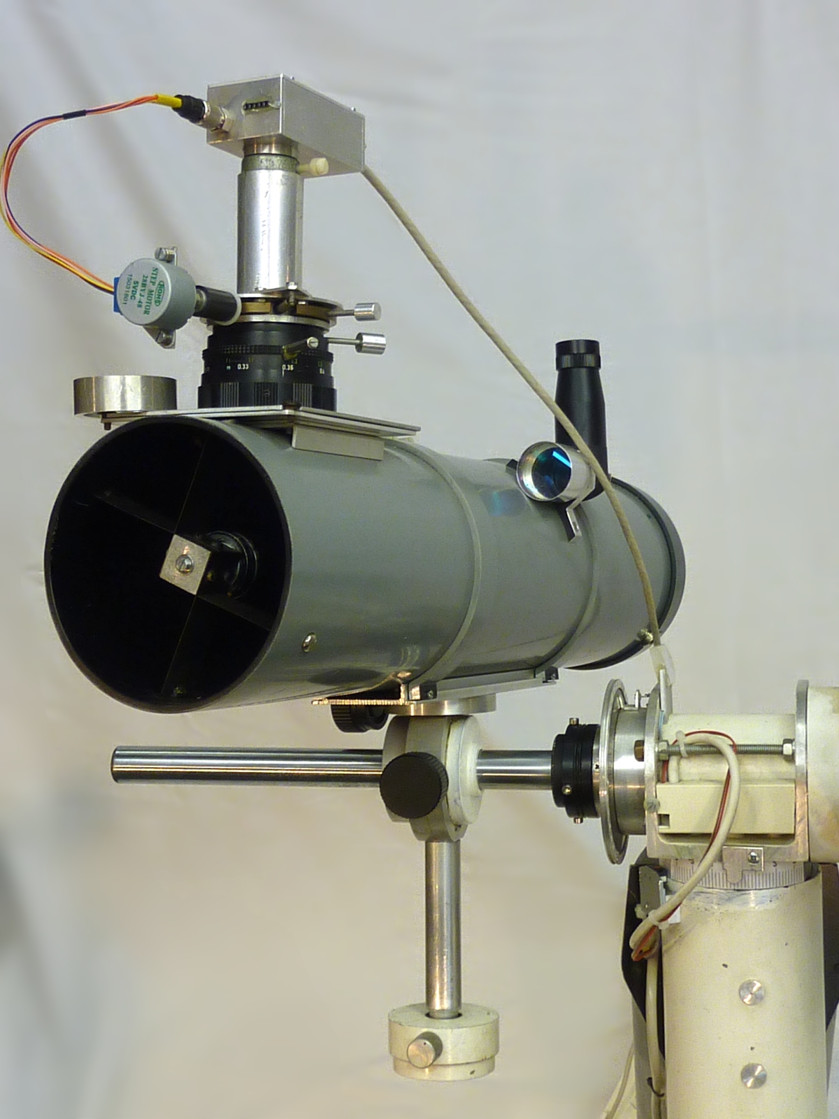
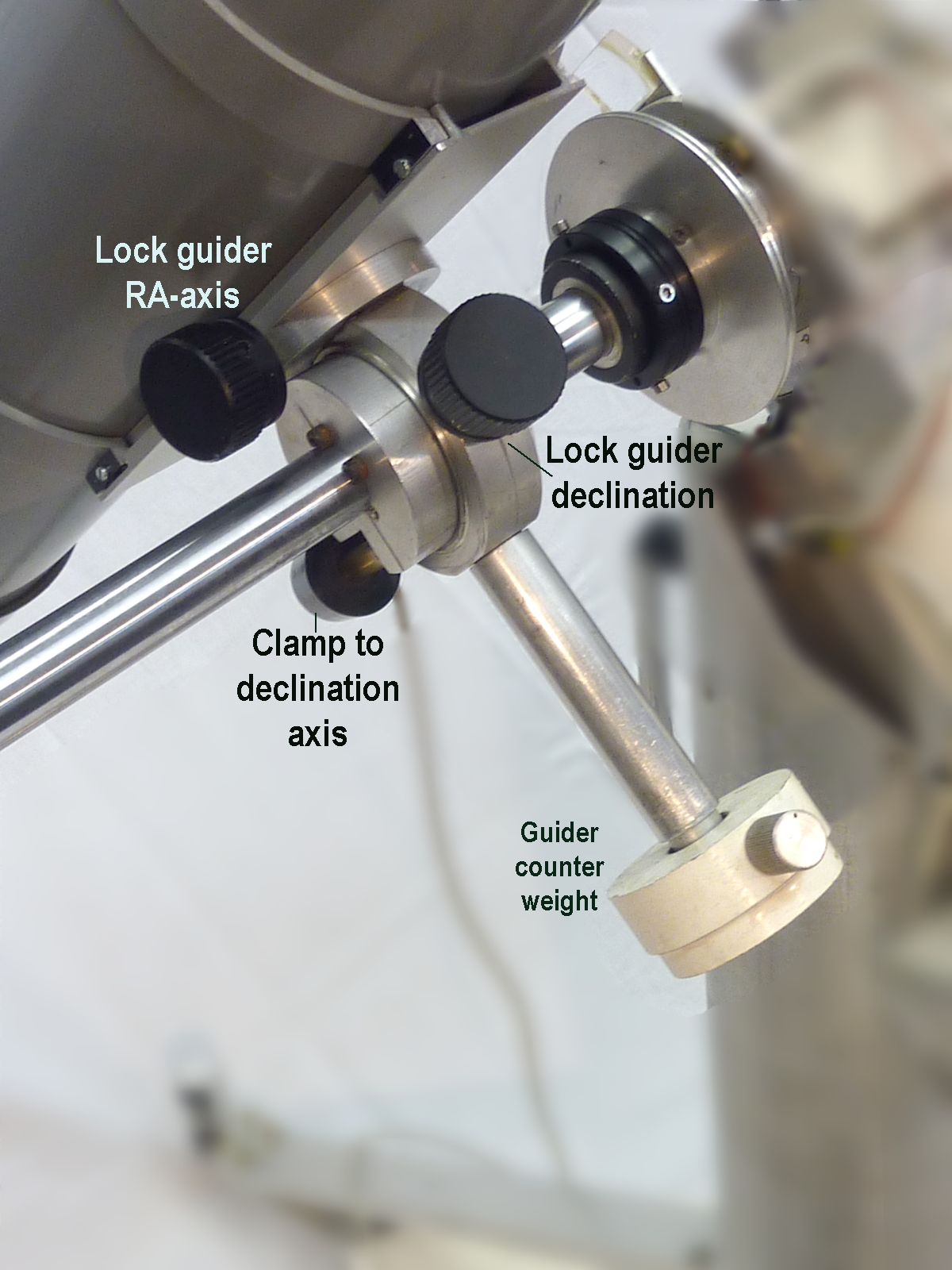
  • Shown here: The guider telescope with 4Q sensor head, the small view-finder (with a very convenient 90-degree angle and, still, upright view) and the guiders own RA- and declination mount, clamped to the counterweight side of the main mount's declination axis.
  • The 4Q-sensor head on the barlow/focusing/centering module. Before placing the 4Q-sensor, the small eyepiece is used for pre-centering the guide star using the North/South and East/West centering adjustments. The focuser uses the mechanics of an old 50mm camera objective.
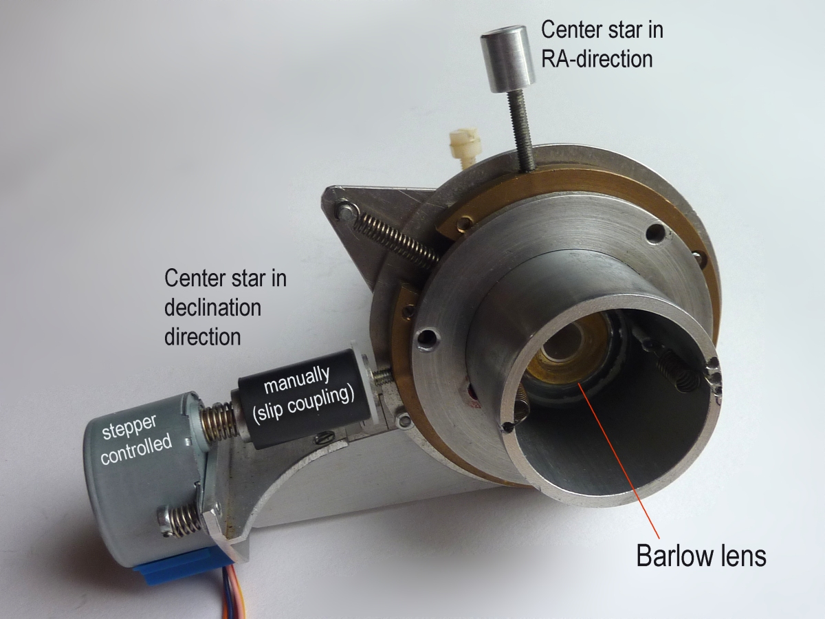
  • A bottom view of the North/South and East/West centering mechanics and the barlow lens. The spring pulls the tube (that fits the focuser) against the lead screws.
  • The quider telescope is clamped on the counterweight side of the declination axis and, while clamped, can be moved freely in RA- and declination direction to aim it at the selected guide star.
  • The 4Q-sensor head and barlow/focuser hardware mounted on the 11-cm Newton telescope.

Principle of the quadrant sensor in one dimension
The 4Q-sensor head with pre-amplifiers
The guider telescope on the declination axis
The barlow/4Q combination
The centering mechanism and barlow lens
Guider mount enabling independent RA- and declination aiming
Photo of the guider scope
Way of working:
After aiming and centering the main telescope on the object of interest, the procedure is to roughly aim the guider scope towards a magnitude 2 (or lower) star that is near this object. Rough alignment is done with the small view-finder attached to the side of the guider telescope tube and using the independent RA- and declination alignment of the guider's mount.
Centering of the guide star is improved using a low magnification eye piece in the focuser. After placing the barlow-tube/centering module, the position of the guide star is observed with a small eye piece with 2x2mm reticle and (finally) centered manually adjusting the North-South and East-West position. Focus of the guide star is optimized.
The signal offsets in North-South and East-West direction of the 4Q-sensor (with the 4Q-sensor head still in the blind holder) are registered using a push button on the mount controller). The 4Q-sensor head is now placed and automatic tracking started (another push-button on the mount controller). The controller will now drive the RA-stepper motor of the equatorial mount such that the error signal from the 4Q-sensor remains as close to zero as possible.
During every dark image taken, the stepper performs a North-South scan to (re)center the guide star on the 4Q-sensor.