 |
 |
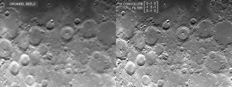
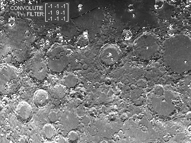
Figure 2:
Effect of 'image edge sharpening' using convolution Upper-left: The orginal image;
Above and left: Processed images of the orginal |
Although image processing may significantly improve the visual quality of the image, it remains essential that the original
image is of an as high as possible quality. This quality concerns three aspects: Contrast, sharpness and noise.
Back to top
Back to homepage
The resulting image contains three components: The dark field, the background caused by the (light polluted) sky and the ideal image of the object. All these components contribute to the total noise of the image. In a pre-processing step the first two components are removed from the image in the following way:
Back to top
Back to homepage
Using the above described pre-processing steps we obtain an image that, besides from having a higher noise level, is equal
to an image obtained in the total absence of stray light and dark current.
SOME DEFINITIONS
Back to top
Back to homepage
Camera with a CCD-sensor chip consisting of a matrix (512x512 or 1024x1024 or other numbers) of small light sensitive
elements (size 8 to 20 micrometer square).
Picture element of a CCD-chip; also picture element of the obtained image.
Image obtained with the un-exposed CCD-camera caused by a thermally generated signal. The intensity of the dark field
varies exponentially with the temperature and thus, cooling the CCD-chip is an effective way to lower this unwanted
contribution. The intensity of the dark field increases linearly with the exposure time.
Image obtained with CCD-camera mounted on the telescope or fitted with its lens, when exposed to a uniform illuminated sky
(i.e.hen clouded or during twilight). The flat field reveals local differences in sensitivity of the optical system
consisting of the telescope/lens and the CCD-chip.
Over-exposure of CCD pixels (e.g. in case of a bright star) causes signal to spill to neighbouring, non-exposed elements
resulting in a local bright blob or bright line in the image.
The conversion of the analog intensity information (electrical charges) from the CCD pixels to a digital number that can
be handled by the computer. A minimum of 8 bits (i.e. the values 0..255), but most often 12 bits (0..4095) or even 16 bits
(0..65535) are used.
The digitized value of the intensity of a CCD-pixel.
Processing of the image by replacing the grey value of each pixel with a new value which is determined by adding and/or
subtracting the grey values of neighbouring pixels in a fixed pattern. This pattern is the so-called convolution matrix.
As an example:
1 5 1
1 1 1
IMAGE ACQUISITION
The first thing to consider is the use of a colour filter to obtain a maximum contrast of details of the object or to
supress the faint glow of night sky (especially in light polluted areas). Emission nebula
(H-alpha and planetary nebula) and planets (mainly Mars and Jupiter) gain from using such filters. When imaging galaxies
and star clusters little can be gained due to the broad spectral emission of these objects.
Focusing of the scope is done (by the author) by taking CCD images in six different (reproducable) positions of the focuser.
These images (or enlarged parts of them) are presented as a 3x2 array in one screen and visualy interpreted. In prime focus,
with stars in the image, unprocessed images will do. When using eyepiece-projection (planets and moon) the changing seeing,
besides focusing, affects image sharpness. In that case sharpness is judged by taking six images for each focusing step.
Before presenting the images on screen, they are processed with an unsharp mask. The focusing position yielding the most and
highest sharpness images is then selected.
With strong changes of the outside temperature it may become necessary to check the image sharpness after some time
since the length of the telescope tube may change and thus shift the focus position.
Noise in the image is caused by two sources: The dark field of the CCD-chip, which depends on the temperature of the chip and
the glow of the night sky which depends on the transparancy of the air and the degree of light pollution at the observation
site. Dark signal and its noise can be strongly reduced by cooling the CCD-chip: Every 7 degrees Celcius gains a factor 2.
The effect of light pollution is something we cannot control (except in some situations by using filters) and results in an
offset (i.e. a minimum grey value) of the image. The magnitude of the noise is in general equal to the square-root of the
signal strength. Thus the lower the dark signal and the darker the night sky the lower the noise.
Especially in case of eyepiece-projection and barlow-projection (and thus photography of planets and details on the moons
surface) it is of great importance that the window sealing the camera and the window sealing the CCD-chip are free of
scratches and dust particles: Due to the large f/D-ratio these blemishes are imaged sharply on the chip and show-up clearly
when using unsharp masking techniques.
PRE-PROCESSING OF IMAGES
A first step of processing the image is usually done during image acquisition: The dark field image (which is obtained by
taking an image with the camera shut) is subtracted from the acquired image. The resulting image thus contains the object,
superimposed on the glow of the night sky and a noise component resulting from the darkfield. This noise is not compensated
when subtracting the dark field because it is random. The lower the dark field signal the lower this noise component.
It is advised to regularly take a new dark field to avoid that, when (later-on) adding images the noise present in the
one dark field image used, shows up as a fixed pattern in the result. Furthermore, for a good compensation it is essential
that the exposure time of the dark field is exactly the same as for the images.
Before subtracting the contribution of the night sky it is essential to correct the image for non-uniform sensitivity across
the CCD caused by inhomogeneous illumination (vignetting) or sensitivity differences between pixels. This so-called flat
field is obtained by taking an (dark field corrected) image of the sky during twilight or when clouded, using the same
optical set-up (i.e. telescope/lens, filter and CCD-camera). The image will show a slow variation in grey value revealing
sensitivity variations within the image. By deviding each image by the flat field image they are corrected for these
sensitivity variations.
To avoid the introduction of noise during this process it is essential to construct the flat field image using multiple
exposures (corrected with the dark field) and smooth the result using a noise filter.
Often a large set of relatively short exposed images is acquired in order to avoid tracking problems from showing up
(especially with home-build equipment!) or to avoid blooming when bright stars are within the image. In prime focus the
exposure time (I use) may be several minutes. With eyepiece projection tracking is usually not the problem and seeing
limits the image sharpness. The best images, showing no tracking errors or with best planetary detail, are selected for
further processing.
By adding several images the noise in the resulting image will be reduced. However, from one image to the other slight
shifts in the position may be present due to (slow) tracking variations. Before adding images this shift should be corrected.
(It can be an advantage when the images are slightly shifted with respect to each other in order to avoid a 'fixed pattern'
from showing up in the added result.)
To optimally fit the images, one image is taken as a reference and the other images are (one by one) shifted in x,y direction
and subtracted from the reference. The best fit is obtained with an x,y shift at which the difference between reference
and image results in noise only. After determining the x,y shifts, all images are added with their appropriate shifts. The
total image intensity will increase linearly with the number of images N, while the total noise increases with the
square root of N. Thus, effectively noise is reduced with the square root of N.
Noise can be reduced by filtering the image using a convolution filter such as: (with N>=1 to select the weight of the central
pixel)
1 N 1
1 1 1
The contribution of the sky is now removed by subtracting a constant value from the image, yielding a black background.
To further remove noise from the nearly black background, I use another non-linear noise filter: Around
each pixel the number of black pixels (i.e grey value = 0) is counted. If this number, including the central pixel, is equal
or larger than 4 (i.e. 4..9) the grey-value of the central pixel is made zero. Is the number equal or larger than 2 (thus
2 or 3) the grey-value of the central pixel is made equal to the mean value of the surrounding pixels. In the other cases
(i.e. the number of zero's is 0 or 1) the grey-value remains unaffected.
IMPROVING IMAGE SHARPNESS
This image can now be processed in order to increase the visibility of details present in the image. In the original image,
these details may have a low contrast or are slightly blurred due to poor seeing or focus errors.
To start with, we have to distinguish between three different techniques that all are aimed at increasing the image
sharpness:
This technique restores a blurred and noisy image by calculating an image that, knowing the noise of the
CCD-camera and the blurring characteristics due to the optical limitations of the scope, is the most probable solution
(i.e. has the highest entropy). MEMs can significantly improve image sharpness using an iterative process with several
(time consuming) Fourier transforms and using the known blurr-function of the optical system.
This technique increase sharpness of edges using convolution filters with a limited size (usually 3x3 or 5x5 see figure 1).
It is especially useful in case of globular clusters and images of the moon for which the edge structures (the stars in the
cluster and the craters on the moon) extend over a few pixels.
It is essential that the original image is nearly noise-free since also noise is 'sharpened' and thus increases. As an
example figure 2 presents an original image of the moon and the effect on this image using different convolution filters.
This technique enhances small structures in the image by removing or weakening the more extended intensity variations in the
image.
 |
 |
Figure 2:
Effect of 'image edge sharpening' using convolution Upper-left: The orginal image;
Above and left: Processed images of the orginal |
Back to top
Back to homepage
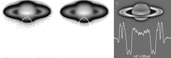
Refer to figure 3 for the next discussion on the unsharp masking technique. It shows images of saturn during different
processing steps. The graph gives the intensity profile of the horizontal line through the middle of the rings.
UNSHARP MASKING
For reasons of simplicity we denote the orginal image by ORG (fig. 3a). ORG consists of a superposition (i.e. a sum)
of an image with a broad, low spatial frequency structure denoted by LF (fig. 3b) and a much weaker image with fine detail
and a high spatial frequency denoted by HF (fig. 3c (streched in intensity)). Thus: ORG=LF+HF.
The unsharp masking technique is aimed at increasing the visibility of the fine structures, and thus of HF contribution,
that are obscured by the large intensity variations (amplitude)of the LF contribution.
 |
 |
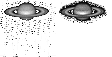
Figuur 3. Unsharp masking visualized using an original image ORG of saturn (3A). The superimposed graph shows the intensity profile over the horizontal line through the center of saturn. 3B is the LF-image obtained using a convolution of ORG with a 11x11 Gaussian convolution filter. 3C is the HF-image obtained by simple arithmics: HF=ORG-LF+offset. 3D and 3E present to possible sharpening algorithms ORG+5*HF and ORG*HF. |
Important for the final result of the unsharp masking action are three aspects
The width of the filter for obtaining the LF-image
The use sharpening algorithm and applied amplification factor of the HF-structure
The presence of artefacts and noise
For the best result of the unsharp masking technique the above mentioned parameters (B, n, offset, method, noise, etc.) should be experimented with. Comparison with images obtained by other amateurs or even professional observatories may be used as a guide in enhancing details up to an acceptable level.