|
The mounting pier holds a German type equatorial mount. Main parts of this mount are the polar axis comprising a couple of radial and thruss bearings, the declination axis that is constructed around a ball bearing pillar and bush (used in plastic molding machines) and the RA-drive comprising a stepper motor and gear train with a 160mm diameter wormwheel attached to the polar axis. The brass wormwheel is made on a lathe (the principle is depicted here): Using an M12-cutting tool in the jaw-chuck, the worm-pattern is cut into the wheel. This is done while pressing the freely rotating brass wheel against this cutting tool. The worm itself is a piece of an M12 threaded bolt which is pressed against the wormwheel and which is spring-loaded. As with every wormwheel (and especially this self constructed one...) there is a periodic error that is corrected for by using the guider telescope with 4Q-position sensor. The worm is driven by a stepper motor (taken from an old inkjet-printer) via a gear train. The speed of the motor is controlled by a microprocessor based on the east-west error signal of the 4Q-sensor on the guiding telescope. The motor can be disengaged to position/adjust the polar axis by hand. |
Images below show the mount and focus on the polar axis and RA-drive. From left to right:
|
 |
 |
 |
 |
 |
 |
 |
|
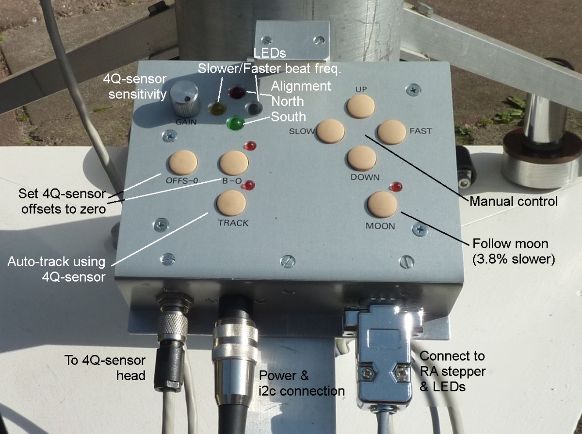
The declination axis can be adjusted by hand using a micrometer screw or using a small 12V DC-motor which is coupled to the micrometer screw through a slip-coupling. The large length of the declination correction arm enables accurate corrections to be made. The pillar of the declination bearing measures 40mm in diameter. It is relatively short and extended with a 22mm diameter rod on which the declination setting circle, the counterweights and the guider telescope are mounted. The polar axis is 30mm in diameter and rotates on two standard ball-bearings which are mounted in a 80mm diameter steel tube. At the position where the declination axis is supported by the polar axis, a thruss ball-bearing is constructed comprising a ring of 4mm balls around the polar axis. A small metal ring retains the balls in their circular track. Near this position the RA setting circle is located which shows the RA-deviation from the exact South orientation. To ease reading of this circle it is printed mirrored while the (LED-illuminated) scale is observed via a mirror. The RA-stepper motor, the DC-motor for declination adjustment and the LEDs illuminating the scales, are controlled from a box attached to the west-leg of the mounting pier and containing a microcontroller and drivers. The 4Q-sensor of the guiding telescope also connects to this box. The mount controller is connected to the 'system controller' . |
Images below focus on the declination axis and the mount controller. From left to right:
|
 |
 |
 |
 |
 |
 |