 |
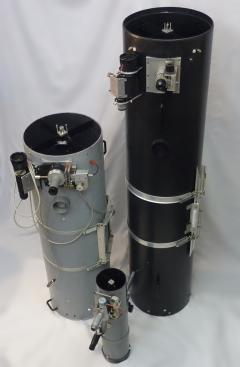
TELESCOPE: Over the years I've built 10cm (4" f/D=4.6), 15cm (6" f/D=6.3) and 25cm (10" f/D=5.7) Newton telescopes. A 25cm (f/D=16) Cassegrain model (initially meant for photographing planets at 4.3m effective focal length) was recently converted to a Newtonian configuration which, combined with a miniscus lens as a simple coma-corrector and focal-reducer, has an effective focal length of 880mm at f/D=3.5. It is specially used for narrow band imaging with my 1kx1k FTT1010-M CCD-camera . |
|
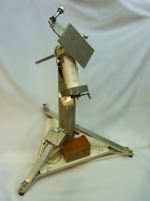 |
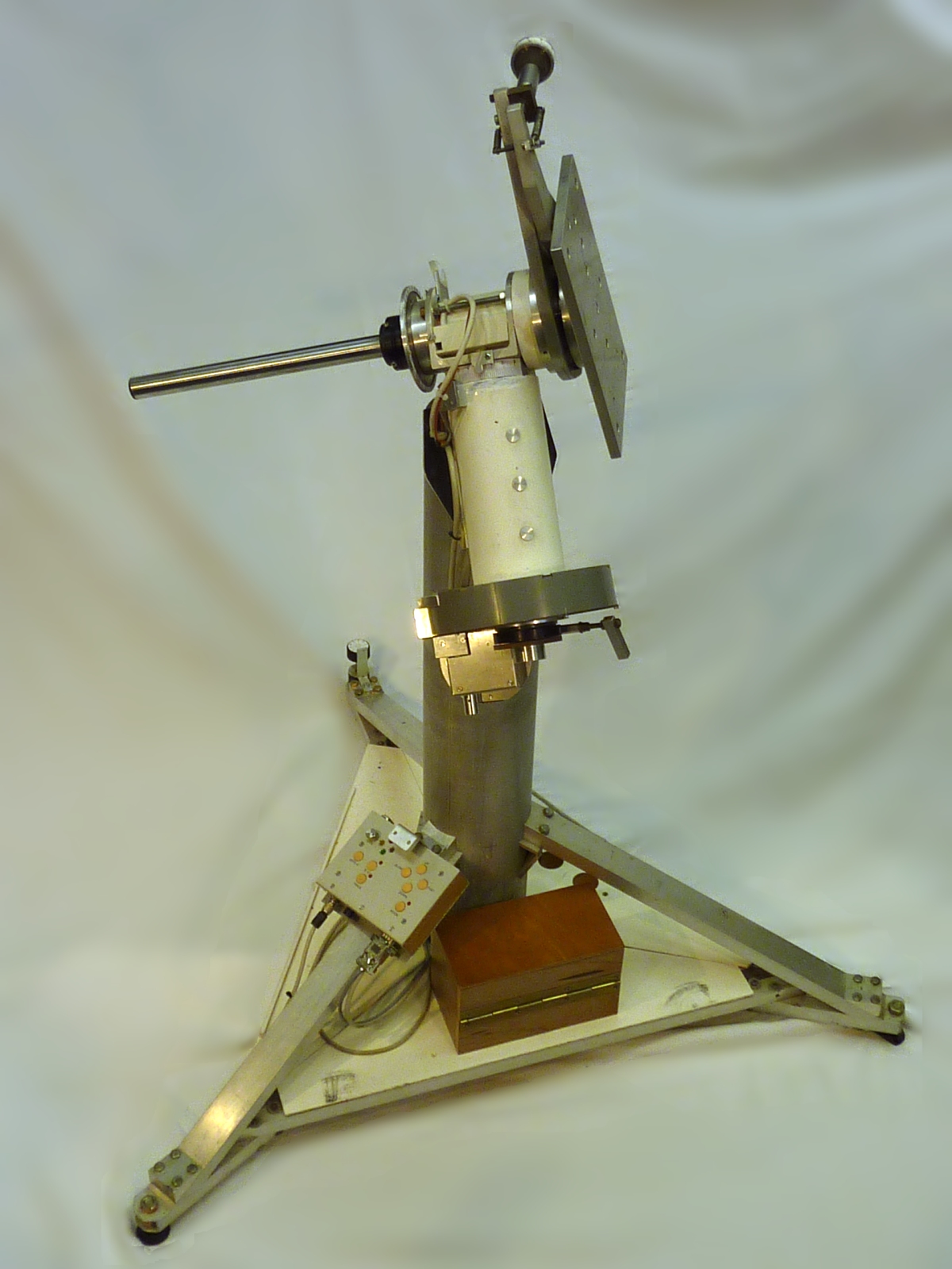
MOUNTING PIER: The mounting pier comprises a central 120mm diameter aluminum pipe and three triangular legs built out of standard aluminum profiles. One of the legs is adjustable in height in order to align the polar axis. With this feature the mounting pier can be used at different locations in my back-yard. At these positions there is a small metal receptacle to which the end of the adjustable leg accurately fits and a metal block that acts as datum for one of the other legs, determining the RA-alignment. The top side of the pier carries the German mount. Click here for some mechanical details and images. |
|
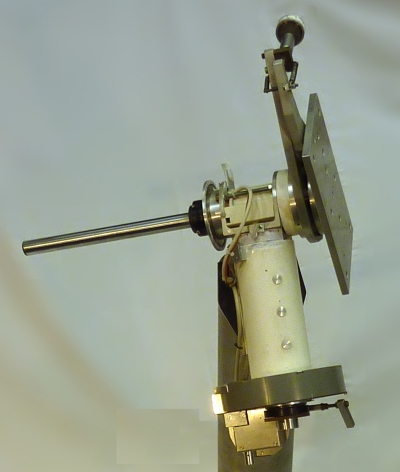 |
GERMAN MOUNT: The mounting pier holds a German type equatorial mount. Main parts of this mount are the polar axis comprising a couple of radial and thruss bearings, the declination axis that is constructed around a ball bearing pillar and bush (used in plastic molding machines) and the RA-drive comprising a stepper motor and gear train with a home-made 160mm diameter wormwheel attached to the polar axis. Click here for a detailed description and some photographs. |
|
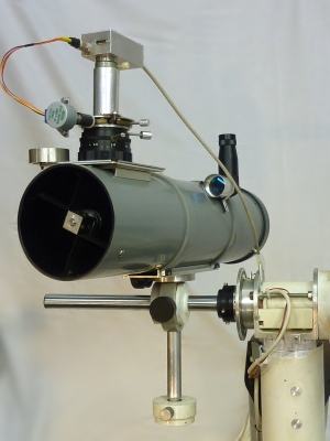 |
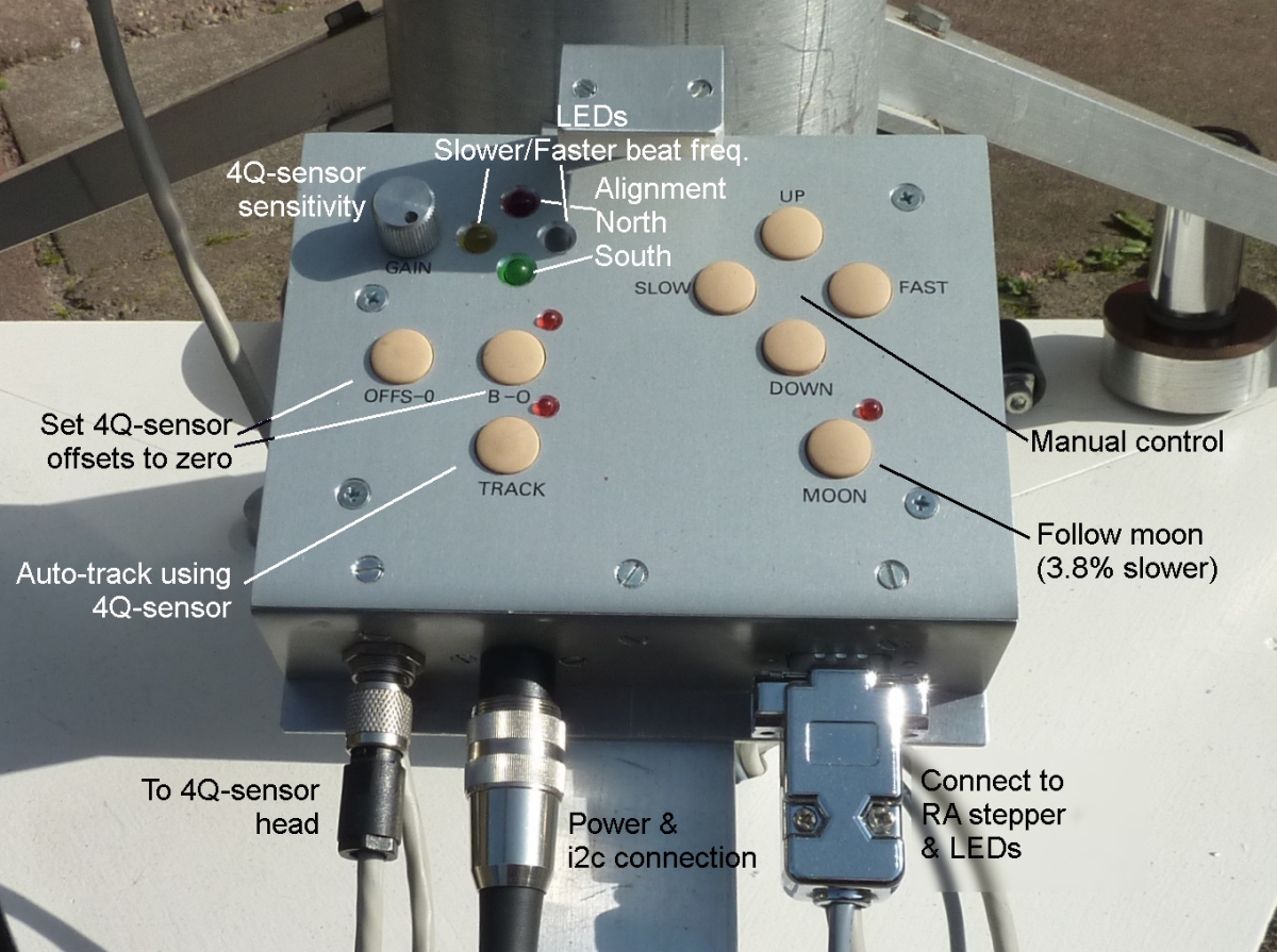
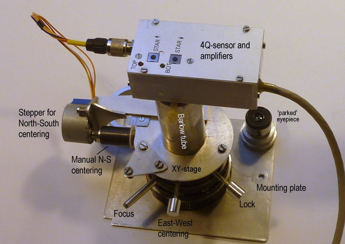
GUIDER SCOPE: The home constructed worm-wheel combination shows a periodic error of approximately 0.5'. To correct for this tracking error, the 11cm Newton scope is used as a guiding telescope (and counter weight): Using a Barlow lens its effective focal length is enlarged to 1.9 meter. A magnitude +2 star (or brighter) is centered on a 2x2mm 4Q-sensor. The mount-controller continuously adapts the RA-stepper frequency to keep the star centered. |
|
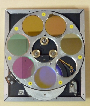 |
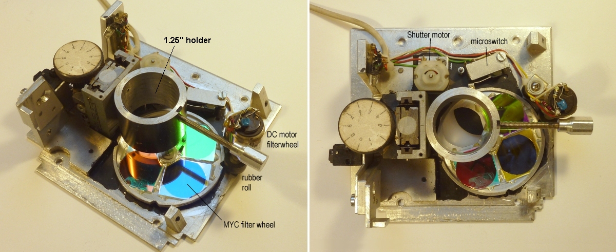
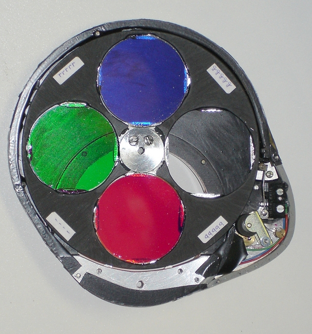
FILTER WHEEL: For colour imaging with the first of my CCD-camera's I used a small MYC-filterwheel (Magenta, Yellow and Cyan), built inside of a 1.25" (31.75mm) manual focusing unit. When the chipsize substantially increased with the FTT1010-M camera, I switched to a larger design, 4-position LRGB-filterwheel (featuring Edmund Optics 50mm diameter RGB-filters). I designed and constructed the filterwheel such that the extra pathlength introduced by the mechanics of the filterwheel is less than 5mm. For additionally imaging in S-II, H-alpha and O-III bands, I constructed a 7-position (i.e. LSHORGB) filterwheel that is also fit for the large FTF2020-M chip (35mm diagonal). For more constructional details and photographs see here. |
|
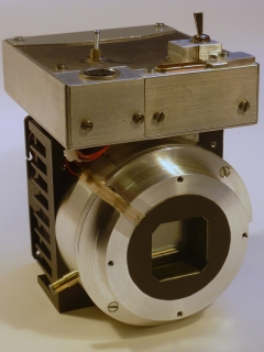 |
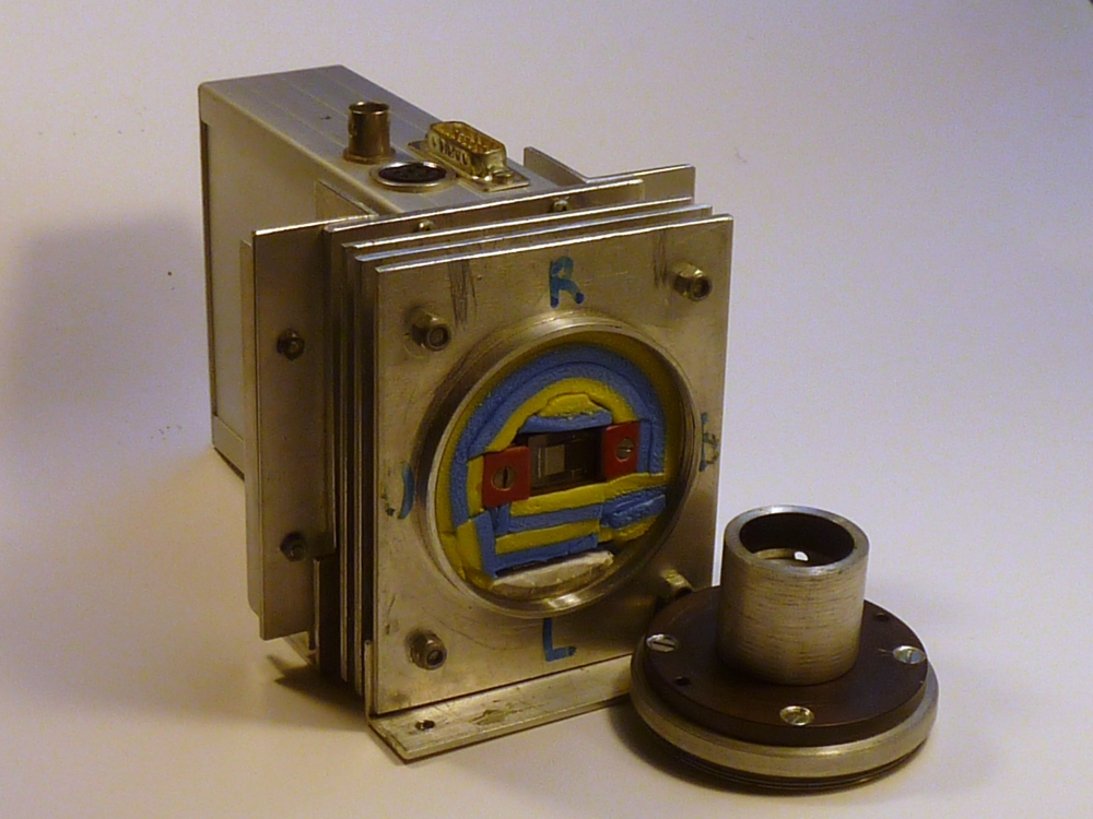
CCD CAMERAS: I designed and built my first CCD-camera in 1993 based on a Texas Instrument, full-frame CCD, the TC211, with 195x165 pixels (sensitive area: 2.6x2.6mm). In 1996 I've got hold of a Philips FT800P frame-transfer chip with a sensitive area of 6.4x4.8mm and 734x580 pixels (HxV). These camera's are out of use. In 1999 I received an FTF1020-C colour CCD chip from Philips Nat-lab and early 2002 Philips surprised me by sending an FTT1010-M and FTF2020-M monochromatic chip. I'm using camera's based on these two CCD's up to this date. |
|
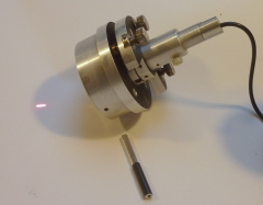 |
LASER COLLIMATOR: Any telescope needs carefull alignment of the optical elements and for the Newton telescope a laser collimator is an indispensable tool. Although the parabolic primary mirror of the telescope performs well on-axis, the spot quality deteriorates towards the edges of the focal pane. This so-called coma gives the spot a comet-like appearance. Especially with large CCD- or CMOS-image formats it is important to center the optics and expel coma to the edges of the field of view. Read here what a collimator could look like and how to use it. |
|
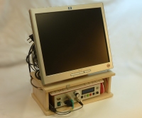 |
SYSTEM CONTROL AND IMAGE ACQUISITION: Many of the above described components (camera, focusing unit, shutter, filterwheel, mount controller and star tracker) are connected to, what I've called, the System Controller. Core is a Raspberry Pi 3B (RPi), but a lot of other hardware is housed into one enclosure. Combined with all cabling, a monitor, keyboard and mouse (KVM) it forms an easy to handle and transport entity. The software running on the RPi takes care of control of all components and the acquisition and storage on USB-stick of acquired raw images. Read more about this here. |
|
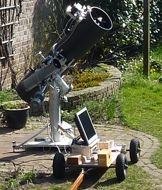 |
TRANSPORT: For a photographing session all components are transported to the observation site (some 50 meters from the storage location) and assembled there. This used to involve a lot of up-and-down walking with equipment, cables, a table and of course, carrying the back-breaking pier/mount. This became a nuisance and was reason (in 2022) to minimize the amount of components and have the System Controller to not only contain the RPi but also power supplies and KVM-peripherals and to construct a cart holding the heavy pier/mount, tracking telescope, counter weights and smaller items. Four trips are enough nowadays, and the setup is up and running in some 30 minutes, while disassembly and storage takes less than 10 minutes. |
|
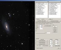 |
PROCESSING SOFTWARE: Processing the acquired raw images is done on a standard laptop and using software that has been in continuous development over the last 25 years. Starting off with a Borland Pascal program I switched to a Windows Visual Studio C++ development environment, which I use up to this date. The program enables aligning and stacking of images and contains functions for noise filtering, sharpening and processing of LRGB images. Some of the features are described in more detail here. |
|
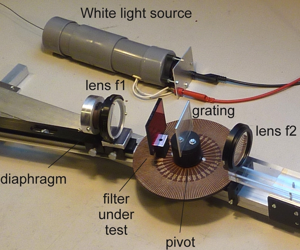 |
MISCELLANY: SPECTROMETER FOR OPTICAL FILTERS: For measuring and checking the transmission curves of my SII, H-alpha, OIII and RGB optical filters I constructed a simple but effective spectrometer using a replicated transmission grating. The spectrometer comprises two arms. The first holds a small white source to illuminate the grating that creates a spectrum, and the optical filter. A second captures this spectrum and focuses it onto an image sensor. Read more about the constructural details here. |
|